Frequently asked question:
Can the IC-2820 be used for standard APRS in FM mode, and can I use the GPS antenna delivered with the DV-option ?
Answer:
Yes, this is possible. By connecting an APRS tracker the IC-2820 can be extended for APRS usage. Please note: we do not talk about D-PRS which works only through D-Star repeaters. We talk about standard APRS in FM which can be done with most transceivers providing a data socket for 1200 Bd packet radio.
This description was done using the Open-Tracker+ but the connection of other trackers is very similar.
When we purchase the IC-2820 including the DV option we also get a GPS antenna. There is no need to buy a separate GPS mouse.
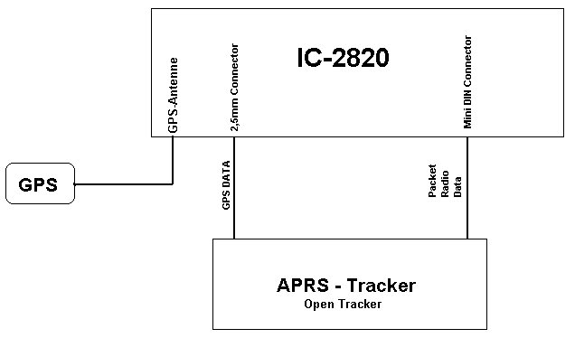
The IC-2820 provides the GPS sentences on it's 2,5mm stereo jack as a serial signal with 4800 Bd. Using an adapter cable we feed this GPS data into the Open-Tracker. The Open-Tracker converts the GPS data into valid APRS messages which are then sent out as a 1200 Bd packet radio signal. With another cable we feed this packet signal into the IC-2820's mini DIN jack.
Unfortunately it is not as easy as plugging in a few cables to get QRV in APRS. ICOM as well as the Open-Tracker engineers have implemented a few problems which we have to handle properly. Here you will find my solutions to get it working:
| The IC-2820 sends the GPS sentences on it's 2,5mm stereo jack. The cassis hole for this jack is very small. The metal ring of a standard 2,5mm stereo jack must be filed off to fit through the hole into the IC-2820's stereo jack. | |
| The IC-2820's serial interface works only if it is connected to a real
RS-232 interface. The COM port of a PC will do the job. You can use i.e.
hyperterminal the view the GPS data (4800 Bd, 1 stop, no Parity, no flow
control). The Open-Tracker (like other trackers) has only an extremely simplified serial interface. If you connect the IC-2820 directly to the Open-Tracker it will not work since the IC-2820 will not send out any data. Therefore the serial output of the Open Tracker must be extended with a standard RS-232 interface, which is described below. |
Usually we want APRS running on the right band of the IC-2820 and we will use the left band for normal operation. To get this working an undocumented trick is necessary:
We configure the IC-2820 for 9600Bd packet but feed 1200Bd packet data into the mini DIN jack. This sounds to be a conflict, but it works and is necessary: Only in the 9600Bd mode the IC-2820 manages the packet PTT and the microphone PTT correctly. The microphone's PTT has priority. Fortunately it is possible to send 1200Bd data even if the IC-2820 is configured for 9600Bd mode. So we can use the comfort of the 9600Bd setting but still send 1200Bd APRS data.The tracker will be connected as described in the IC-2820's manual shown for the 1200Bd packet mode.
Then we set the IC-2820's menu to 9600Bd packet in the right band and tune this band to the APRS frequency (in Europe 144,800 MHz).
The Open-Tracker needs a 12volts power supply, we usually use the same power which is used for the IC-2820. But whether ICOM nor the tracker engineers have implemented a way to switch the tracker on/off simultaneously with the IC-2820's power.
The only switched power of the IC-2820 is the 8 volts output on the microphone jack. It delivers 10mA max. which is too low for any tracker. But this 8 volt output can be used as control voltage to switch the tracker on/off using a simple transistor circuit.
When all these actions are done, you are QRV in APRS.
Please find here the details of my modifications. Before implementing it by yourself please make sure that you really understand all the details, since I'm not responsible for any typing errors or other mistakes !
To make the IC-2820 sending out GPS data it is necessary that the serial
input of the IC-2820 has a voltage of about -8 volts (which is the standard
RS-232 HIGH-level). Without this negative voltage the IC-2820 will not send
anything.
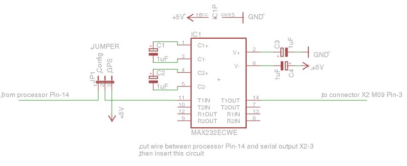
I use the well known MAX-232 circuit to generate this voltage.
When the jumper is in the "GPS" position, the MAX-232 will have -8 volts on the output and the IC-2820 will send GPS data.
When you want to configure the Open-Tracker using the PC-software set the jumper to "Config" and connect the tracker to your PC.
When you build this small circuit into the Open-tracker then cut the line from the processor pin-14 to the connector X-2 pin-3 and insert the circuit as shown above.
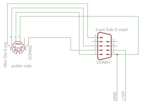
This drawing shows the wiring between the Open-tracker and the IC-2820.
The mini DIN connected is viewed on its soldering pins, like it is shown in the IC-2820 manual.
| Function | Mini-DIN Pin | 9-pol Jack PIN |
| Audio to IC-E2820 | 1 | 1 |
| Squelch | 6 | 2 |
| PTT | 3 | 3 |
| Audio to Tracker | 5 | 5 |
| Ground | 2 | 6 |
| +12V | --- | 7 |
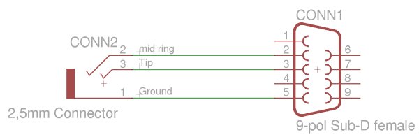
Connect the 2,5mm stereo jack with the tracker as shown in the drawing. This cable can also be used for the CS-2820 software or similar.
The Open-Tracker+ needs about 30 mA. This is extremely low current for a car
battery, so if you want you can connect it permanently and ignore this
description.
By the way, the standby current of the IC-2820 is 10 mA.
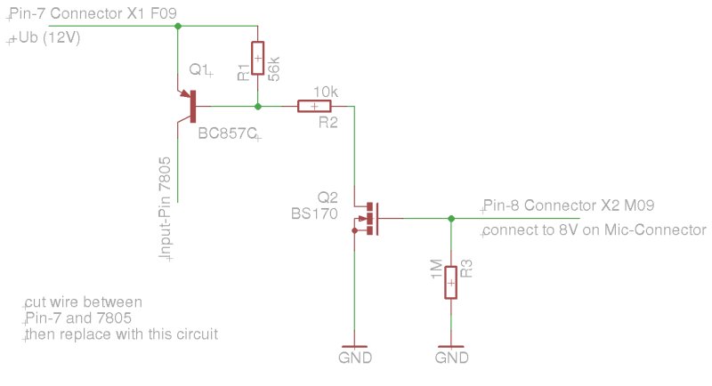
This circuit is required the switch on/off the Open-Tracker with the IC-2820's control voltage. This control voltage is available on the microphone jack (8 volts, see the IC-2820 manual).
The input pin of the 7805 regulator in the Open-Tracker must be separated for the input voltage and the circuit shown above must be inserted into this line.
Good Luck, See You In APRS !