It is hard to radiate a sufficiant amount of power on the 630m band since the efficiency of usual antennas is very poor (< 1%). Therefore we need to generate a lot of power. This document describes an amplifier using four MOSFETs with an efficiency of > 90%.
Highlights:
* up to 650 watts on 474,2 kHz (Ub=37V)
* input power only 1 watts
* efficiency >90%
* supply: 12 to 40 volts
* cheap but powerful MOSFETs
Output Power:
| Supply- Voltage [V] |
DC Current [A] |
Output Power [Watts at 50 ohms] |
| 13,8 | 7,6 | 100 |
| 15 | 8,1 | 121 |
| 20 | 10,5 | 200 |
| 24 | 12,7 | 290 |
| 26 | 14 | 350 |
| 28 | 15,5 | 425 |
| 30 | 17,5 | 507 |
| 35,6 | 19 | 600 (good cooling required !) |
Transistors:
The MOSFET IRFP4227 is the ideal transistor for this type of amplifiers. We have tested a lot of MOSFETs in TO247 and TO220 case, but got the best results using the IRFP4227. A single MOSFET can produce up to 200 watts, in a push-pull amplifier. To get more power and to have comfortable reservers we use two Mosfets in parallel. We can run this circuit with 500 watts continous output. With a more powerful supply we could also run at 650 watts or even more.
Sicherheitsmaßnahmen:
Please be warned: powers of several 100 watts could generate arcs of light or other damages. Therefore always waer protective goggles when working on the open amplifier. The output voltage can be more than 160 volts eff. which is a dangerous voltage. Please handle the output lines with respect and never touch them during operation !
We build a couple of measurement and security circuits into the amp:
* over temperature switch
* volt meter connector
* amp meter connector and current sensor
* emerency stop relais
Bill of Material:
BOM for purchasing material for this amplifier
Circuit diagram of the power section (click on the picture to zoom):
with a small double hole core we generate two signals, shifted in phase by 180 deg. This signals are first limited by 15v Zener diodes and fed into the TC4422 MOSFET driver chip. This driver limits it again routes it trough a Schmitt-Trigger and finally controls the gates of the power mosfets. These driver can handle up to 4nF capacitive load which perfectly fits to the IRFP4427.
0.1 ohms resistors on the Souce pins are used to evenly distribute the power to each mosfet. Without these resistors one mosfet would do all the job and the other would do nothing (like in real life, hi). The mosfets are connected to a big ferrit ring core which is described later.
A 2-stage low pass filter is connected to the output. This filter is extremely important not only for damping harmonics but also to show the optimum reactance to the amplifier. Without this filter the output power and efficiency would be very poor.
The supply current is filtered by two ferrite cores and a couple of capacitors. These capacitors must handle a lot of RF current. Therefore only big and robust types can be used: FKP1 for caps < 1uF and switching stable electroly caps > 1uF.
Input Requirements:
This PA works with an input power of 1 watts. Only the input voltage is important, so the PA's input impedance is high. If your controlling transmitter needs a 50 ohms load, then simply place a resistor (i.e. 100 Ohms / 3 Watts) in parallel to the input. This is not required for the U02 DDS controller so you can save a little power.
Circuit diagram of the control part (click on the picture to zoom):
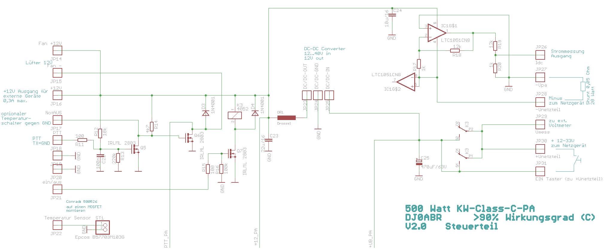
the PTT control circuit is shown on the left side. Pull the PTT input to GND and the amplifier will be switched into transmit modem the input and output relais are ON and the PA is ready to use. With an optional temperature switch we can switch-off the PTT if the heatsink temperature exceeds some value.
To the right we find the amplifier for the DC current measurement. A shunt resistor is placed in the negative power supply and the voltage across this shunt is amplified by a Null-offset chopper OP. This voltage represents the DC current and can be measured with some instruments.
The main power relais (right side in the circuit diagram) is a 16A relais (12 volts). When the power is connected the relais is still open and no power goes to the amp. As soon as a little key is pressed the relais switches on and stays on. If the power breaks down (i.e. due to a shortcut) the relais opens and does not close again without user interaction. This is a simple but important security feature.
Output circuit:
The output circuit is the most complex part of this circuit.
We need a real big toroid core for 500 watts. The best results were achieved with the biggest toroid from Wuerth Electronics. Many, many try and error loops were necessary to find the number of turns. The best results for a operating voltage of 26 to 33 v are 2x2 primary and 12 secondary windings. For a 24v supply the better choice is 2x1 and 8 windings.
Theoretically you can increase the output power by increasing the number of secondary turns. But this is limited by the iron and copper losses in the toroid. Therefore it is extremely important to use wires with the largest possible surface. The surface is important, not the diameter, because at 500 kc only the outer layer of 65um is used by the current. A copper foil or the shield of a coaxial cable is a good choice (silvered is even better). (We did not get satisfying results with RF braid).
The capacitors at the MOSFETs and parallel to the toroid have to be high voltage FKP1 types, 1000 volts minimum. This is required because the current through this resistors is high and high voltage caps can carry these currents.
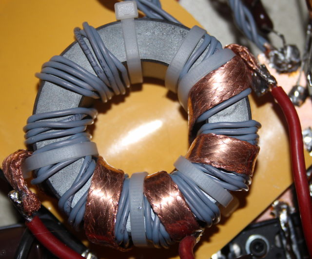
The output toroid core:
this pictures shows my toroid useable up to 700 watts.
First the secondary winding is made of 4 times 0,5 mm² silicone wire. A
single 1,5mm² wire gives the same results.
I am using silicone cable because it is heat resistant and very easy to wind, it
is easily available from flight-model shops.
The primary winding is made from copper taken from a coaxial cable and heavily flattened. A silvered type would even give better results.
The core itself is non conductive. But the toroid must be mounted carefully to make no shorts.
The Resistors:
As often stated Mosfets have a positive temperature coefficient. If temperature rises, the drain-source resistance Rds rises and automatically balances the currents between the paralleled Mosfets. This is right, but in this circuit not enough for a good current distribution. Therefore we use additionally 0,1 ohms resistors. They have a maximum voltage drop of 1 volts, which is a good value for proper balancing of the mosfets. The efficiency loss of 1% is acceptable.
The PCB:
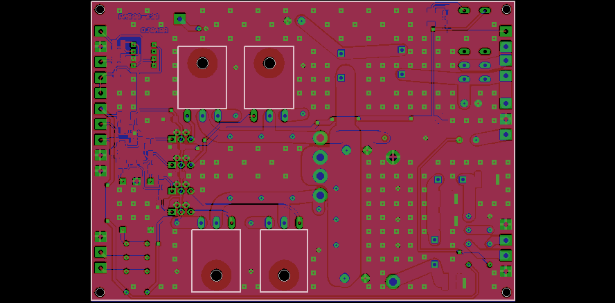
the PCB has the dimensions 155x110 mm., The toroid is not mounted on the PCB but mounted above it
Due to the good efficiency a relativly small heatsink is sufficiant. However if you plan to run 500 watts continuously you should consider using a bigger heat sink because cold MOSFETs have a better efficiency then hot ones !
Components (click to enlarge):

Anschlüsse:
| Netzteil minus (nicht GND) | 1) power supply, negative line. The negative line must not
be connected to the PE (protecive earth) in order to get the current
sensor running. 2) one pin of the current shunt resistor |
| GND (Shunt) | second pin of the current shunt |
| I(dc) Messausgang | Output: DC voltage which is proportional to the current consumption. For the connection of an instrument to show the supply current |
| +12V/1,5A Ausgang | 12V / 1,5A Output: for external devices |
| FAN (Lüfter) pos. | positive connection for a fan, is active during transmission only. |
| FAN (Lüfter) neg. | negative connection for a fan, is active during transmission only. |
| Emerg-OFF (Notabschaltung) | Connecting this pin to GND switches OFF the PTT. Usage: i.e. connect a temperature switch to disable the PTT if the temperature is too high. |
| PTT (TX=GND) | PTT connection. Pulling this pin to GND switches the amp to TX mode |
| RX-Bypass | connect these pins with a thin coaxial cable. In RX mode the antenna is switch to these pins. |
| 475kHz IN / 1W | Input of the amplifier. It needs approx. 1 watts |
| Power Relais (GND=off, >3v=ON) | connecting this pin to +12V enables the main power relais. This pin may be used for an emergency power-off controlled by an external circuit. |
| U(dc) Messausgang | Output: power supply voltage output for an external volt meter. |
| Netzteil pos. (13,8..35V) | power supply positive line. Minimum 13,8V and maximum 35 volts (abt. 15 to 30 A max) |
| EIN Taster | Connect a push-switch here and the other pin of the switch
to "Netzteil pos. (13,8..35V)". The main power relais is switched ON is this switch is pushed. |
| zum DC/DC Wandler | positive line of the power supply. Connect the input of a 12v regulator (DC/DC converter with 3A minimum) |
| +12V vom DC/DC Wandler | connect the output of the 12v regulator here |
| Antenne | Antenna connector |
Minimum required connections:
if you don't need all the sensor and measurement outputs, then the minimum required signals are:
* Power supply neg. and pos.
* DC/DC Converter
* Antenna
* 475kHz IN / 1W
* PTT
* Power Relais (GND=off, >3v=ON) connect to +12v
* ON push switch
PCBs:
We have a couple of spare PCBs, if you are interested please contact our club.
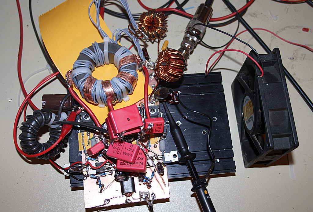
The prototype:
this picture shows the fully functional prototype. Even if it looks like a pile of scrap this bunch of electronic parts generates up to 650 watts of power. The efficiency is good and the cooling fan unnecessary.