Especially during WSPR operation one uses very low transmit power of just a few mW up to a few Watts. Normal power meters do not indicate accurately or at all with this low power. Only in connection with a capable detector with software support can accuracies of better than 1 dB be achieved.
We followed an idea that DH5RAE had and used the AD8307 for that purpose. This logarithmic amplifier is well known in amateur circles and used in a number of projects already. So you ask what makes this board special and how does it compare to other AD8307 projects ?
One priority: it should not remain a prototype, but this board should work well when built by others. The step from a proof on concept prototype to a repeatable solution took quite a bit of time - but it has been accomplished.
| two AD8307 are used, one for forward and one for backward power | |
| the construction works without adjustments and is therefore easy to build | |
| the necessary calibration is done automatically by software | |
| the values are reported to the DDS board and enable the automatic and precise adjustment of the transmit power | |
| the values are also reported to the PC or Smartphone in case one wants to use the Power Meter as a test instrument |
In the meantime the project has matured and several boards were built. Below you find the construction info and test results. As in all U02 projects all of this is freely made available to Hams and whoever wants boards can get in touch with us.
The Measuring Bridge:
We decided to use a Hybrid Coupler for this measuring bridge. It is not normally used in commercial ham gear as it is a bit more expensive. However it has the great advantage that it does not require adjustments or tuning. I built properly it works well from the get go. In our units $3 more or less make little difference so we can select this luxury variant. As a reward we get a coupler which will provide accurate results even in the single digit mW range.
The circuit is made up of two identical ring cores which together with two 50 Ohm reference resistors make up the measuring bridge.
To fit these cores to our board we need two FT61A-43 Amidon ring cores (ferrites).
These get each 50 windings with 0.35 CuL wire. That is more than used in similar circuits but has shown that it will provide the best results from 630m to the 6m band.
As little as 10 Milliwatt are sufficient to measure the SWR of an antenna accurately.
The construction of the coupler has been explained well in Wikipedia and therefore does not need to be repeated here.
First Step: Preparing the Coax Ring Core transformers
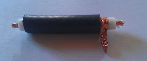
We use a short piece of Aircell-7 coax cable. One can also take any other but this one fits well into the FT61A-43 ferrite core. The cable piece will be prepared exactly as shown in the pictures. It is less important how it looks but most important they both parts look alike
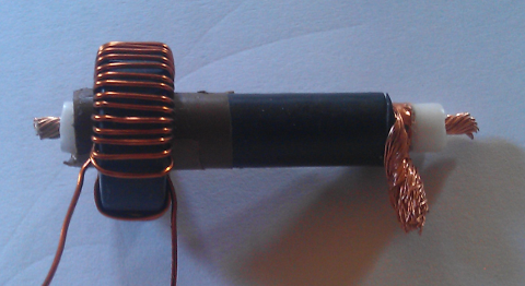
Now prepare the two Amidon ring ferrite cores with exactly 50 windings of CuL 0.35 wire and make sure that the coating is not damaged. Check again the number of windings and compare both items.
Then slide the completed core onto the coax. The wire end from the top is shown on the left and the lower one on the right. When installing and wiring them the left one will connect to the other coax’s shield, the right one goes to the other coax/s center conductor.
DIAGRAM of the Measurement Amplifier (to resize click on it):
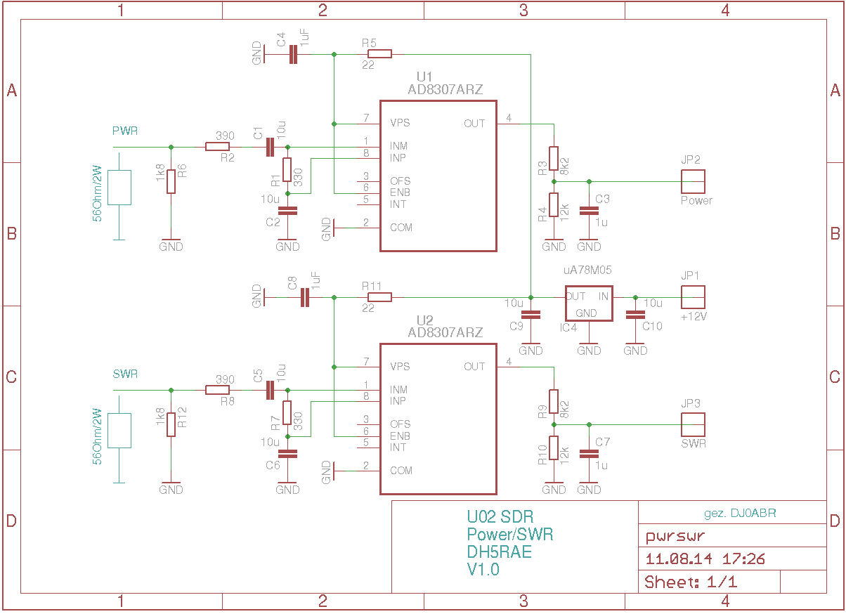
Part of the measuring bridge are the 50 Ohm reference resistors. In this case we created the resistor out of a number of single resistors. In fact it is a 56 Ohm resister with a 1.8 Ohm resister in parallel and then another combination of a 390 Ohm, 330 Ohm and the internal resistance of the AD8307 paralleled with the first two. All together this give us 50 Ohms exactly.
The two resistors of 390 Ohm and 330 Ohm form the input voltage divider. This is necessary to avoid exceeding the max input power of +17 dBm of the AD8307. The divider is designed so that power levels from below 1 mW to 300 W can be measured.
The 56 Ohm resistor is a larger 2 W metal film resistor and is soldered directly. It will absorb most of the energy in higher power levels. The other resistors are on the board itself.
The AD8307 amplify the measurement signal and create a DC voltage which can be converted directly into dBm. This voltage can be tapped at the pins “POWER” and “SWR”. Ahead is a voltage divider. Its only purpose is to adapt the output voltage of the AD8307 to the analogue input of the uCs on the DDS board. Should the measurement bridge be used for a different purpose (i.e. with a cross pointer instrument) this divider can be left off or changed in values.
KEINE AHNUNG WAS RICHTSCHAERFE IST AUF ENGLISCH.
The directivity limits the lowest measurable SWR. Between 160m and 10m one can measure better than 1:1.05. In Median wave on the 630m band one reaches 1:1.1 and on 6m still 1:1.18
These accuracies are achieved on a reproducible board build with normal effort. It is quite possible to achieve even better results if one is willing to spend a longer time to guarantee a symmetric measurement bridge. However the result is already better by a large margin compare to most commercially available units.
CONNECTION AND EVALUATION:
This board was developed for the U02 DDS but is universally usable.
Following the connection of the transmitter output and the antenna as well as the 12 V power supply one connects the outputs for “Power” and “SWR” with the identical ones on the input side of the U02-DDS. All else is accomplished by the software of the DDS. Power as well as SWR will be indicated in the display.
PLEASE CONSIDER THE FOLLOWING HINTS IF YOU WANT TO BUILD YOUR OWN TEST INSTRUMENT:
To do a correct calculation one needs two items:
1) a reference value, what output voltage (DC) does the AD8307 provide at a specific power level (dBm)
2) the increment in Volt / dB at the board output (Power and SWR output are identical)
with these two values one can now easily calculate any power level.
To give an example measured on by board:
transmit power 9 Watt / 39.54 dBm … voltage at board output 0.95 Volt
transmit power 0.563 Watt / 27 dBm …. voltage at board output 0.825 Volt
the increment is 0.95 - 0.824 = 0.125 V divided by 12.04 dBm (39.54 - 27.5)
resulting in 0.01038 V or 10.38 mV per dBm.
With that the transmit power can be calculated:
Transmit power in dBm = 39.54 + (output value - 0.95) / 0.01038
Calculating the SWR:
Now we can calculate the forward and backward power in Watt.
The SWR is the forward and backward voltage relationship. This we first need to convert the power to voltage at 50 Ohm for both forward and backward voltage and then the SWR.
These calculations can be done with small micro controllers.
CONNECTING A CROSS POINTER INDICATOR:
This is the easy part as all one needs to do is connect the two outputs to the two instrument inputs and one is done. To adjust the sensitivity of the instrument one replaces the voltage divider with a potentiometer.