There is a Micro Controller with its firmware on the DDS board. In order to adjust various functions we use PC software. The board gets connected to a PC, the software gets started and the needed functions are adjusted. These will be stored on the board which then can operatewithout a PC.This configuration software runs under Windows, Linux and MAC. If using Linux or MAC on needs to preinstall the “mono” packet.
Here is an overview of the various windows:
Function Selection:
![]()
this is where the basic functions of the board are selected.
WSPR-Beacon:
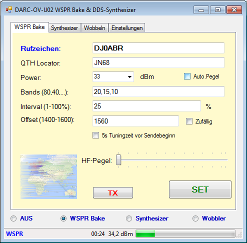
The details needed for WSPR are entered here - like call sign, QTH Locator (in 4 digit format) and the output power.In the field “Band” one can enter in a comma delimited format all wanted bands. In the above example that would be 20, 15 and 10m “Intervall” determines how many pauses should be made in between the transmissions. Using 25% the beacon will transmit in every forth time interval (one time interval in WSPR is 2 minutes) which means it will transmit every 8 minutes. If using 33% it would be every third, and 50% every second etc.“Offset” tells the transmit frequency inside the WSPR band. That goes from 1400 to 1600 and one can select a frequency in this range. If one clicks on“random” this setting changes automatically with every transmission. This is interesting when using very low power levels (< 100 mW) so thatone does not collide with stronger stations all the time.“5s Tuning time” is clicked when using an automatic antenna tuner. This allows to transmit a carrier 2 seconds before the actual data transmission to allow the tuner to match the antenna.Finally one adjusts the RF power output. If using the PWR/SWR board this is handled automatically.Clicking the “TX” button triggers the transmission in the next interval
CW Beacon:
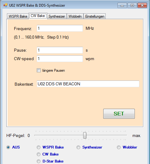
The CW beacon works like others. The CW ID will be sent in definable time segments. In addition on can vary the transmit power level so that the beacon works different cycles with different power levels.The text and the speed of the CW output is adjustable. One can also extend the character spacing which may be more pleasing to copy.The CW beacon is not only useful for normal beacon operation but can also be of use to test potential future repeater locations ahead of time.
D-Star Beacon:
The D-Star beacon can play a previously recorded text. Like the CW beacon the power level can also be varied.A special function is the built-in bit error generator. This allows to test what bit error rate a D-Star receiver can take before audio becomes garbled.The recording of the text is done with a DVRPTR and the control centersoftware. As there are more than 1000 of these in use today it should not be too difficult to find someone who can record such a text. This audio file will then be copied into the D-Star Beacon.
DDS Synthesizer:
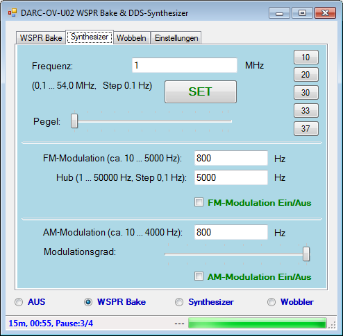
You enter the frequency and adjust with the slider the power level. If you have the 5W amp and the PWR/SWR board you can also select the level directly.The board then transmits on the entered frequency.This frequency can be modulated in FM or AM. Just click on the appropriate box. If one wants to change the modulation entries one switches the box on or off to take over the new values.
Sweep Generator:
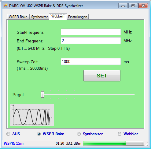
The sweep generator allows operation in a range from 0.1 to 54 MHz inan adjustable time span.This function is ideal to tune for example filters. Also the pass band of IF filters, TX low pass filters and RX bandwidths can be determined with it.
Settings:
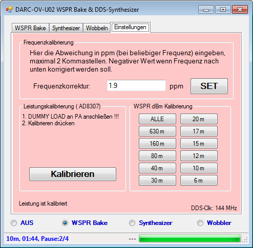
Frequency Calibration:
Use a shortwave receiver with a 10 MHz time signal. Then program the DDS board to 10 MHz. The receiver will then play both signals. Now change the transmit frequency of the board until there is zero beatwith the time signal. The difference (delta) will then be entered in ppm (parts per million). As we are using 10 MHz we divide the difference number by 10 and enter the value.Example:The DDS board transmits on exactly 10 MHz when adjusted to 10.000025 MHz.So the delta is 25 Hz. With reference to 1 MHz that is 25/10 - 2.5 ppm. This value is entered and then click on SET. This makes the board transmit on the exact frequency. It is recommended to let the board warm up for 10 minutes before making this adjustment.Of course if you have an exact frequency counter you can measure this value directly.
Power Calibration:
These adjustments are necessary if you use the 5W amp and the PWR/SWR board. On can calibrate these boards in such a way that thetransmit power can be measured to better than 1 dBm.You need a 50 Ohm dummy load and a scope which is accurate on 7 MHz. Of course if you have one available that is accurate even on 28 or50 MHz this is an advantage but not absolutely necessary.
Stand-Alone Operation:
Once the WSPR entries and adjustments have been made you can turn off the PC. The board will operate free standing. The entries have been stored and will be kept even after power was disconnected and reconnected. The beacon will resume operation automatically.