DSP-7 works with any power/SWR measurement hardware which delivers a voltage linear to the measured power in dBm.
The most used hardware is the Analog Devices AD8307. The output voltage of this chip must be adjusted (i.e. by a voltage divider) to have a maximum value of 2.4 volts. Then it can be used together with the DSP-7 controller.
Calibrating the DSP-7 to the power/SWR hardware:
calibration is made at two power levels. The best accuracy will be achieved if one power level is as low as possible (min) and the other is as high as possible (max).
Touch CALIB ![]() to
open the calibration menu.
to
open the calibration menu.
The DSP-7 can handle three Power/SWR bridges simultaneously. Therefore the display offers three settings:
For use in an Power Amplifier Controller:
Pwr/SWR-Bridge1: ANT (this bridge is connected at the antenna output)
Pwr/SWR-Bridge1: FLT (this bridge is connected between the amp and the low pass
filter)
Pwr/SWR-Bridge1: IN (this bridge is connected at the input, measuring the drive
power)
(if DSP-7 is used in a tripple Power/SWR measurement instrument, the three bridges can be used as needed, with no special assignment).
Overview:
Calibration is a very simple process and can be done in a few minutes:
* Transmit with a low power and measure the output voltage of your Pwr/Swr bridge.
* Do the same with a high (max) power.
* Do it for all Power/Swr bridges used (up to three).
![]()
The calibration in detail:
! for calibration connect a good 50 ohms dummy load !
we need to tell the controller which voltage is generated by the Power/SWR brigde at two different power levels. Then the controller can calculate all other values automatically.
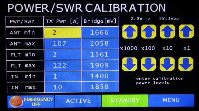
For calibration we have to enter the transmitter power (in watts) and the voltage (in mV) generated by our bridge. We do this for the minimum possible power and for the maximum possible power.
Choose a output power:
Touch ANT min and enter the minumim power your transceiver is able to
transmit.
Then set the transceiver to FM and press the PTT and adjust the output power to
the minimum power level ANT min.
The most reliable way to measure the power is using an oscilloskope, connect it parallel to the 50 ohms dummy load and measure the peak-peak voltage. See the help above the arrow buttons. It shows the Vpp corresponding to a output power. Adjust the output power until the scope shoes this Vpp value.
Now touch the Bridge[mV] coloumn in the same line, the display changes:
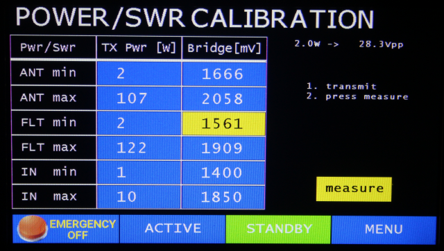
while still transmitting press the "measure" button. Now DSP-7 measure the voltage of your bridge and enters this value in millivolts into the grid.
Do the same for the ANT max, the maximum power you can generate.
Now repeat this process for the other two bridges.
When finished press MENU, this will save the calibration values.