The board DSP-7 can be used as a controller for ham radio power amplifiers (low bands, short wave, VHF/UHF/SHF) and also as a display for power/SWR meters (simultaneous single, dual or triple swr bridges).
This document describes the various inputs and outputs.
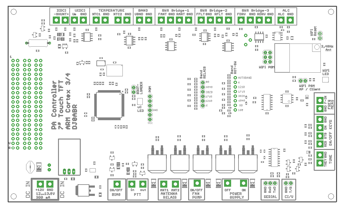
Location on the board (connectors are labeled directly on the board):
beginning with the connector at the top left and continuing clockwise:
| Function | Connector | Description |
| I[DC] | - SHUNT | inputs to measure the amp's power supply current. Connect these pins to a shunt resistor in the positiv power supply. See remark-2 on shunt resistor values and scaling. This pin goes to the amplifier side |
| + SHUNT | and this pin goes to the power supply side of the shunt resistor. | |
| U[DC] | Um, GND | input to measure the amp's power supply voltage. Usually this pin can be directly connected to -SHUNT. See remark-3 on scaling. |
| TEMPERATURE | NTC1, GND | Measure temperature No.1. Connect a NTC resistor type: B57703M103G (10kohms) |
| NTC2. GND | Measure temperature No.2. Connect a NTC resistor type: B57703M103G (10kohms) | |
| BAND | UBND, GND | input for automatic band switching. Icom compatible. If connected to the DATA port of an Icom transceiver, pin: "band", then you can select AUTO (band selection either via touch panel or rotary switch) and the band will be switched automatically. |
| SWR Bridge-1 | FANT, GND | connect the forward measurement voltage of a power/SWR board. See remark-1 |
| RANT, GND | connect the reverse measurement voltage of a power/SWR board. See remark-1 | |
| SWR Bridge-2 | FFLT, GND | connect the forward measurement voltage of a power/SWR board. See remark-1 |
| RFLT, GND | connect the reverse measurement voltage of a power/SWR board. See remark-1 | |
| SWR Bridge-3 | FDRV, GND | connect the forward measurement voltage of a power/SWR board. See remark-1 |
| RDRV, GND | connect the reverse measurement voltage of a power/SWR board. See remark-1 | |
| ALC | ALC, GND | ALC output to reduce the transceiver's output power depending on the amplifier's current consumption (adjustable) |
| FREQ MEAS | F_IN, GND | connect to the RF input (i.e. via a cap or resistor) to measure the frequency of the transceiver. |
| ON/OFF KEYS | RES | connect to GND via a push button. If pressed the controller does an emergency shutoff. The same function is available as touch button in the display. |
| STB | connect to GND via a push button. Each touch toggles between active and standby mode. The same function is available as touch button in the display. | |
| ON | connect to GND via a push button. If pressed the controller activates the power supply and goes into standby. The same function is available as touch button in the display. | |
| TUNE | TKEY | may be connected to the TKEY line between an ICOM Transceiver and a tuner. The controller will automatically switch into standby during tuning. |
| CI/V | T/R, GND | Icom CI/V serial bus. For future use. |
| SERIAL | RxD, TxD, GND | universal serial interface. Used to flash new firmware via a PC serial interface. |
| POWER SUPPLY | ON | goes to GND in Standby mode, see comment-5. |
| OFF | goes to GND in an emergency situation, see comment-5. | |
| FAN, PUMP | ON/OFF | will be pulled to GND in the temperature exceeds the adjustable limit to switch ON a fan or water pump. A +12V fan or pump can be directly connected here (other fan/pump pin to +12V) |
| ANTENNA RELAIS | ANT1 | will be pulled to GND to activate antenna-relais no.1, see remark-4 |
| ANT2 | will be pulled to GND to activate antenna-relais no.2, see remark-4 | |
| PTT | in | connect to the PTT output of a transceiver (open=RX, GND=TX) |
| out | connect to the PTT input of the power amplifier (open=RX, GND=TX) | |
| BIAS | ON/OFF | +12V output, connect to the BIAS voltage generation of the amp. Will be switched ON only during transmission. |
| 12..13,8V | +12V, GND | power supply of this controller board and the display. Connect to the 12V station power or a separate 12V/300mA supply. (voltage may be between 10 and 15 volts). |
additional pin headers in the middle of the board:
| Function | Connector | Description |
| BAND RELAIS | 80 | connect to a relais (via a driver transistor) to
activate the corresponding band in the output filter. This output goes to
3,3V if activated. If no output is active then the 160m band is selected.
These outputs can have 4 different band configurations selectable in the SYSTEM menu of the firmware. |
| 60/40 | ||
| 30/20 | ||
| 17/15 | ||
| 12/10 | ||
| 6 | ||
| BAND ROT SWITCH | 160 | these pins can be connected to a rotary switch (common pin of this switch to GND). If connected the band can be selected by this switch. If not connected the bands can be selected by touch buttons in the display. |
| 80 | ||
| 60/40 | ||
| 30/20 | ||
| 17/15 | ||
| 12/10 | ||
| 6 | ||
| AUTOBAND | ||
| BAND ROT SWITCH, Alternate Functions |
160 | if not used for band selection, these pins can be connected to PTTs of up to 4 transceivers. Together with a relais-board these pins are used as an input selector. |
| 80 | ||
| 60/40 | ||
| 30/20 | ||
| BOOTLOADER | Jumper present | Connect these two pins with a jumper and switch ON the power. The controller goes into the boot loader mode and waits for a new firmware via the serial interface. See firmware update instructions. |
| not jumpered | normal operation | |
| WIFI PGM API/CLIENT | Jumper present | when powered-up with this jumper present then the WiFi Interface starts its own AP (access point, no password). A WiFi device (PC, smartphone...) can login this AP. Open a browser and enter this IP: 192.168.1.4 to show the controller webserver. |
| not jumpered | when powered-up without jumper then die WiFi interface tries to log into your loacal network as a client. WiFi-LED: blue: logon in process, green: login successful. Use the AP mode above to enter your local WiFi ID and password. | |
| WiFi RESET | short these pins to reset the WiFi interface | |
| WiFi PGM | Jumper present | the WiFi interface is connected to the controller and the build in webserver shows the controller status and values |
| not jumpered | a serial interface (3,3V levels !!!) can be connected here to flash new firmware into the WiFi interface. DO NOT connect directly to a PCs RS232 interface, instead always us a voltage converter. |
Remark-1a : Power/SWR bridges when used as a power amp controller
this controller can handle the output voltages of up to three Power/SWR bridges.
Bridge 1 (Connector FWD_ANT and REV_ANT): this bridge is located at the antenna output of the amplifier. Its usage is mandatory since most security functions use the power and SWR measurement results.
Bridge 2 (Connector FWD_F and REV_F): can be used optionally but is highly recommended. It is used to detect defective low pass filters or if a wrong low pass filter is selected. The security function to protect the amp in case of a wrong filter is only working if this power/SWR bridge is installed.
Bridge 3 (Connector DRIVE): can be used optionally: this bridge is connected directly to the input plug of the amplifier and measures the drive power. Only the forward voltage of the bridge is used. The amplifier will be switched off in case of too high drive power. Additionally the usage of the ALC is recommended.
Remark-1b : Power/SWR bridges when used as a Power/SWR measurement instrument
this controller can handle the output voltages of up to three Power/SWR bridges. Any possible brigde may be connected, see requirements below. This allows to build a Pwr/Swr instrument which can simultaneously measure SW, VHF/UHF or SHF power and SWR values.
note about Power/SWR bridges::
you can use power/swr boards based on the AD8307 logarithmic amplifier. The output voltage at full power may be 2,4 volts maximum. This controller has a menu to calibrate the power/swr bridges by software, so the exact voltage is not important.
Pwer/SWR boards are available here: http://www.helitron.de/shop (not everything translated into english yet).
Remark-2: Shunt Resistors
This controller supports four current ranges: 10A, 50A, 100A and 200A
When a range is selected in the System-Menu, a shunt resistor must be used according to this table:
| Range | Shunt |
| 10A | 5 milliohms |
| 50A | 2 milliohms |
| 100A | 1 milliohms |
| 200A | 0.5 milliohms |
Remark-3: Scaling of voltage measurement
This controller supports four voltage ranges: 50V , 100V, 1000V, 4000V
the range 50V and 100V are supported by resistors already mounted on the board.
For the 1kV and 4kV range an additional voltage devider must be mounted externally. This devider (two resistors) must be mounted close to the power supply and far away from the controller to avoid high voltages at the controller board.
| Range | Shunt |
| 50V | close solder bridge on the controller board |
| 100V | default |
| 1kV | add external voltage devider |
| 4kV | add external voltage devider |
External Resistors:
Rp : connect in parallel to the controller board input (connect to pins Um and GND)
Rv: connect between measured voltage and input pin Um1kV range: Rp=5,6kohms, Rv=2,2Mohms (solder bridge on the controller board: open)
4kV range: Rp=4,3kohms, Rv=6,8Mohms (solder bridge on the controller board: open)
Remark-4: Antenna Relais
The controller supports three antenna outputs selected by two relais. This diagram shows how the relais are connected:
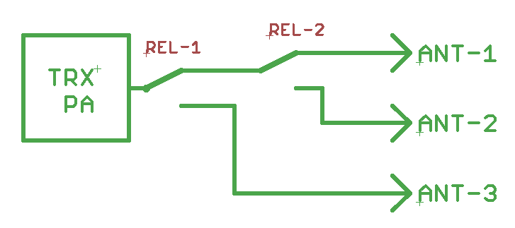
Connect output pin ANT-1 to relais REL-1 and output pin ANT-2 to REL-2.
Connect the other relais pins to +12V
A reverse diode is not required because it is already on the controller board.
Use the Antenne-Menu to assign bands to each of the three antennas.
Remark-5: ON/OFF Relais for the power supply
The board has two outputs to drive 12V relais directly (the reverse diode is already on the board).
POWER SUPPLY ON:
This output goes to GND if the controller is switched on (STANDBY mode). If the controller is switched to ACTIVE mode then this output goes to high impedance, a relais will be switched off.
This is an important security feature: Connect a relais in a self-holding circuit. In ACTIV mode this output is inactive, but due to the self-holding the relais is still switched ON. If an error occurs in the power supply then the seld-holded relais can switch off automatically. It is not "forced" to ON.
If the HELITRON Over-currect security switch is used, connect this pin to the ON-Relais of the switch.
POWER SUPPLY OFF:
the output is high impedance during normal operation and goes to GND in case of an emergeny situation.
If the HELITRON Over-currect security switch is used, connect this pin to the OFF-Relais of the switch.
A red warning LED could be also connected here (via a resistor to +12V).