Connections
New boards avalable: see HERE.
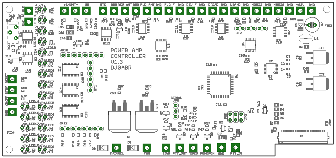
The wires to the controller are located at big and easy to solder pads at the top and bottom of the board. Wires for the band selection are located at pins in the board as described here:
Connections to the big labeled soldering pads:
(the connectors are described her beginning at the top right, and then counter clockwise):
| Connector | Function | Remarks |
| GND (multiple soldering pads) | Ground is connected to the negative power supply | |
| +12V (+13,8V) | Power supply for this controller and the connected parts (i.e. relais). | connect it to a suppy of 10 to 15 volts, min. 200mA. The usual 13,8V station supply can be used. |
| MISC1 | not used | for future extensions |
| MISC2 | not used | for future extensions |
| UBAND | optional: input for automatic band switching. Icom compatible. | Connect this line to the DATA port of an Icom transceiver, pin: "band" (Icom ACC plug). To activate the autoband function connect the lowest pin of ST1 to ground (the first pin close to the label ST1). |
| DRIVE | optional: connect the forward measurement voltage of a power/SWR board connected to the input of the amp. | see details below, Add. 1 |
| REV_F | optional: connect the reverse measurement voltage of a power/SWR board connected between the amp and the low pass filter | see details below, Add. 1 |
| FWD_F | optional: connect the forward measurement voltage of a power/SWR board connected between the amp and the low pass filter | see details below, Add. 1 |
| FWD_ANT | connect the forward measurement voltage of a power/SWR board connected between the amp and the antenna output | see details below, Add. 1 |
| REV_ANT | connect the reverse measurement voltage of a power/SWR board connected between the amp and the antenna output | see details below, Add. 1 |
| NTC | Temperaturesensor Typ: B57703M103G | Connect the sensor to this pin and GND |
| UB | input to measure the amp's power supply voltage | usually connect this pin directly to the pin SHUNT- |
| SHUNT- und SHUNT+ | inputs to measure the amp's power supply current. Connect these pins to a shunt resistor 2,5mOhms in the positiv power supply | Range 0 - 60A. |
| ALC | optional: ALC output to reduce the transceiver's output power | connect to the ALC plug of your transceiver. It is highly recommended to use this conection ! |
| RESET | Connect to a push-button on your front panel labeled "OFF". (other button pin to GND) | Push this button to switch the amp OFF and go into idle mode. |
| STBY | Connect to a push-button on your front panel labeled "Standby/Active". (other button pin to GND) | Push this button to switch between standby and active mode. In standby mode the PTT output in inactive (always in RX mode) |
| ONOFF | Connect to a push-button on your front panel labeled "ON". (other button pin to GND) | Push this button to switch the amp ON. |
| MAINREL | optional: connect this output to a power relais which switches the mains power supply. Connect the other pin of the relais to +12V. | will be switched off in case of errors |
| FAN | optional: connect this pin to a fan (or a pump in case of water cooling). Other pin of the fan to +12V | the fan will be activated at a temperature of +38degC and deactivated at +35degC. |
| BIAS | optional: +12V output, connect to the BIAS voltage generation of the amp. | will be switched off in case of errors |
| PTT_OUT | output: connect to the PTT input of the amp | will be pulled to GND in TX mode. Open in RX mode. |
| MISC0 | not used | for future extensions |
| PTT_IN | input: connect to the PTT line of your transceiver |
Connection to a 8-pole rotary switch for band selection:
| JP12 - 1 | rotary switch, position 6m |
| JP12 - 2 | GND |
| JP12 - 3 | rotary switch, position 10+12m |
| JP12 - 4 | rotary switch, position 15+17m |
| JP12 - 5 | rotary switch, position 20+30m |
| JP12 - 6 | rotary switch, position 40+60m |
| JP12 - 7 | rotary switch, position 80m |
| JP12 - 8 | unused |
| ST1 - 1 | rotary switch, position: automatic band selection (Icom) |
Only 7 positions of the 8-pole switch are connected. If the unconnected position is selected then the 160m band is activated.
Connection to the relais of a low pass filter:
these outputs are normally GND (0 volts). If a band is activated then the corresponding output goes to +3,3v. Maximum load: 5mA. Connect a transistor (N-channel mosfet) to switch the relais.
| JP15 - 1 | unused |
| JP15 - 2 | unbenutzt |
| JP15 - 3 | Output 6m |
| JP15 - 4 | Output 10+12m |
| JP15 - 5 | Output 15+17m |
| JP15 - 6 | Output 20+30m |
| JP15 - 7 | Output 40+60m |
| JP15 - 8 | Output 80m |
if no output is active then choose the 160m band. This is a quasi standard with todays low pass filter boards.
Add 1 : Power/SWR bridges
this controller can handle to output voltages of up to three Power/SWR bridges.
Bridge 1 (Connector FWD_ANT and REV_ANT): this bridge is located at the antenna output of the amplifier. Its usage is mandatory since most security functions use the power and SWR measurement results.
Bridge 2 (Connector FWD_F and REV_F): can be used optionally but is highly recommended. It is used to detect defective low pass filters or if a wrong low pass filter is selected. The security function to protect the amp in case of a wrong filter is only working if this power/SWR bridge is installed.
Bridge 3 (Connector DRIVE): can be used optionally: this bridge is connected directly to the input plug of the amplifier and measures the drive power. Only the forward voltage of the bridge is used. The amplifier will be switched off in case of too high drive power. Additionally the usage of the ALC is recommended. Please be aware that LDMOS transistors are very robust at the output but very sensitive at the input.
a note to Power/SWR bridges::
you can use power/swr boards based on the AD8307 logarithmic amplifier. The output voltage at full power may be 2,4 volts maximum. This controller has a menu to calibrate the power/swr bridges by software, so the exact voltage is not important.
Pwer/SWR boards are available here: http://www.helitron.de/shop (not everything translated into english yet).