Building a 1kW amp was a hard job ... until now. The new LDMOS transistors make it easy to generate a lot of power in the short wave bands. The designs published in Youtube are very simple, most are working, but many important parts are missing. Specially security circuits for the sensitive gate are missing. One transistor costs >$200, so we have to take care that we do not exceed the maximum ratings of the LDMOS transistors.
The design:
many OMs have build LDMOS amps, but my favorite design was made by W6PQL He did a very clever layout which reduces stray inductance and allows stable operation over a wide frequency range..
But even this nice design lacks of some important circuits which, for me, is a must for every power amp. So I completed the design with these parts::
| RX/TX switch by two relais (a small relais at the input and a power relais at the output | |
| TVS Diodes in the input to protect the gate of the expensive LDMOS, I am implementing a two-stage protection. | |
| optional compensation capacitors | |
| good RF blocking in the power supply lines | |
| a modified layout which allows to use one odr two LDMOS or even other RF-Mosfets | |
| separate BIAS circuits for the upper and lower transistor part. Allows cancelling out the first harmonic | |
| Snubber Gate-Resistors to attenuate parasitic oscillations, only required if two LDSMOS are used | |
| more physical space for the transformers for cores up to 2kW and more | |
| very powerful output balun | |
| connection for an external input attenuator | |
| optimised layout to reduce line inductance for DC currents >50A | |
| air- or optional water cooling | |
| all connections required for an external amplifier-controller | |
| external over-current protection |
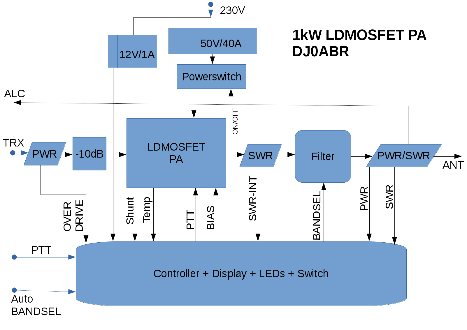
Blockdiagram of the complete amplifier. The PA board the the box in the middle "LDMOSFET PA":
Security circuits:
- Input drive power measurement, switches OFF if input power is too high
- checking if the correct output low pass filter is connected
- measurement of the antenne SWR
- current consumption
- voltage from the power supply
- temperature (cooler)
if a dangerous situation is detected the amplifier is switch off.
LEDs:
- ON
- TX
- 160m
- 80m
- 60+40m
- 30+20m
- 17+15m
- 12+10m
- temperature too high
- antenna SWR > 1:2
- overcurrent
- supply voltage error
- wrong low pass filter
switches:
- ON
- Standby
- OFF (Error-Reset)
- band selection (1.8 - 60 MHZ, or auto-select)
power supply:
- PS 12V/1A for the controller and the reais
- PS 50V/40A for the amp
Cooling:
a copper heat spreader mounted to an aluminium cooler is fine the SSB or short CW transmission. For long CW transmissions a water cooler has a much better performance.