Stage-2: the 30W PA
the 10W amplifier for es'hail-2 was designed because we need a cost efficient replacement for the Chinese Wifi Booster. With a cost of material of less then 25 Eur this goal was reached.
But what means: 10 watts ?
10w is the peak power of the amplifier where it goes into compression. If a constant carrier is sent, the power is max. 10 watts (i.e. CW or SSTV or similar).
But in SSB this looks different. The volume of an SSB signal (human voice) leads to a lower average output power. To make the signal stronger the SSB transceivers have an integrated speech compressor which amplifies the quiet signals more than the loud signals.
An example:
An 20m short wave transceiver is set to full power and the output power is measured with an averaging Pwr meter (not a modern peak power meter):
Constant carrier: 100 watts
SSB: 25 watts
SSB with speech compressor: 35 watts
we can see that a 10 watt amplifier is ok, but will not generate a booming loud SSB signal. With an 80cm dish and a good feed 10 watts is sufficient for a reasonable signal. But for a very good signal or a smaller dish (i.e. camping dish) we need more power. This was the design goal for the 30 watt booster.
Schematic (click for a high resolution picture):
Circuit description:
the BLF2425M9L30 works as an class-A amplifier.
An 78L05 generates a stable 5V bias voltage which is set with R10 and temperature stabilized with R11 (If you cannot get this NTC then use a 5k6 resistor).
A PTT circuit shuts down the quiescent current during RX. So if you want to test this amplifier, connect PTT to ground.Set the quiescent current to 200mA by turning R10.
The input and output matching is made according the reference circuit, but recalculated for an FR4 material 0.6mm thick.
The loss of FR4 does not allow to get the full 30 watts specified for this transistor, but was choosen for minimum costs.
C18 and C25 are not mounted, they are for tuning, but looks to be not required.
Layout:
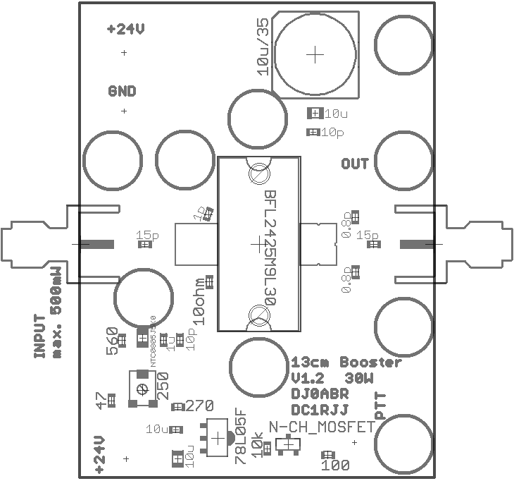
Building hints:
solder the SMA connectors directly, and as close as possible, to the board. It is NOT sufficiant to use a metal housing as a ground connection !
The board must be screwed directly to a cooler. Before soldering the board use fine sand paper to make the bottom of the board flat, remove all rough edges, be carefully, don't remove to much material from the ground plane, just the rough parts.
Sand paper the cooler and remove the black anodic coating. The cooler is used as a ground connection between the transistor and the board.
Screw the board to the cooler using 9 screws, use ALL of them, this is very important !
When the board is mounted, mount the transistor. DO NOT solder the transistor before all screws are fastened. Soldering the transistor is the very last action. The pads of the transistor are little bit above the PCB. Using a screw driver carefully bent the pads down to the PCB (alternatively a mounting slot can be milled into the cooler to bring the transistor down for about 0.5mm, but most people will not be able to do that, and it is not necessary).
Use thermal compound under the transistor, but only use a very small amount of paste that is almost transparent. A bigger amount of paste will isolate the ground connection !
Commissioning:
First of all: I am NOT responsible for any damage or malfunction. If you build this amplifier you should know what you are doing and you are responsible by yourself. All documents are release under the GNU public license v3 (see HERE).
The PTT input should be connected to the PTT output of your transceiver.
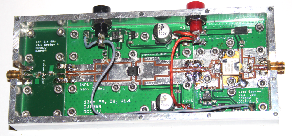
Stacking the 10W amp and this 30W amp:
the position of the RF input and output lines are at exactly the same position on all boards. To place the 30w amp just after the 10w amp is easy, simply mount the boards one after the other and connect the 10w output with the 30w input with a solder bridge ore a small piece of wire, See this example: