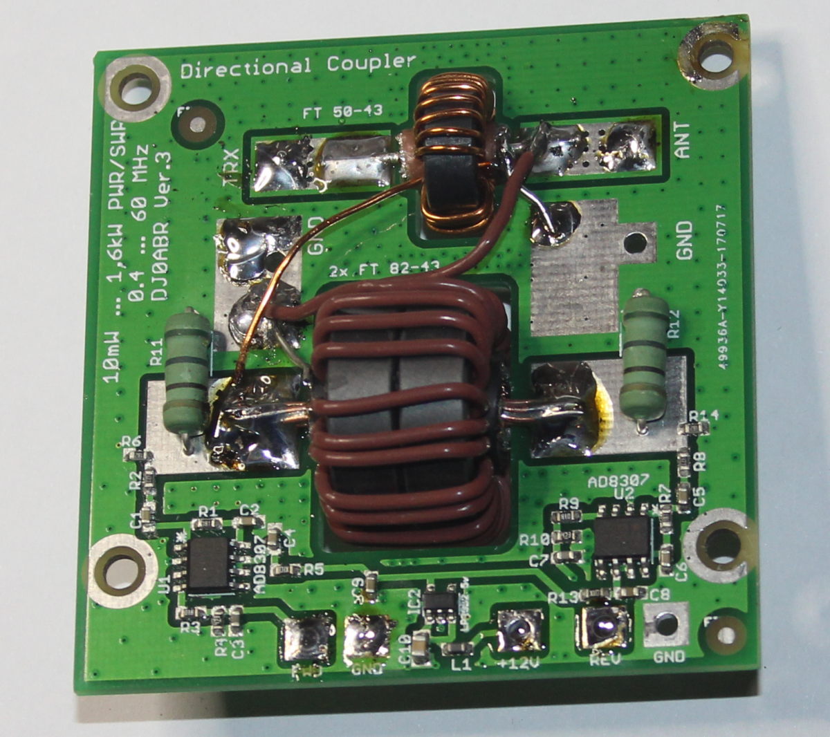
Version-2: Board without housing
This second version of a Sontheimer / Frederik-Koppler was developed as part of our 1kW-LDMOS-PA project. The focus of this coupler is on a wide power range and a wide frequency range. Measurements of 1mW have been omitted, but the coupler has been optimized to over 2kW, thus ideally suited for power amplifiers.
Very important was also the simple construction. The annoying mechanical work for the production of tinplate housings had to be dispensed with.
Specifications of this short-wave power / SWR coupler:
| Power range: 100 mW to 2 kW | |
| Frequency range: 0.4 MHz to 60 MHz (630m to 6m band), with reduced accuracy also in the 4m band usable | |
| Directional sharpness on all bands> 30dB (on 70 MHz> 20dB) | |
| Construction on a single board which also contains the two ring cores | |
| Two AD8307 are used, one for the leading and one for the returning power | |
| The circuit operates completely without adjustment and is therefore easy to set up |
> Link to the real measured values <
The circuit of the first version has turned out to be optimal, so it has been adopted unchanged. The mechanical design as well as the dimensioning of the ring cores were mainly modified. Thanks to a specially calculated circuit board layout, a good adaptation could be achieved without housing.
The directional sharpness and thus the resolution of the SWR measurement is so precise that even the influence of adapter plugs (PL-N etc.) is clearly measurable. Also, the quality of coaxial cables can be measured. Of course, a precise dummy load (with exactly 50 ohms) is required.
Ring cores, size:
This coupler uses 2 ring cores and is thus free of any adjustment.
Ring core 1: this sits directly above the connection transceiver <-> antenna. This wire is passed through the core once (ie, 1 turn). This core measures the current flowing from the transceiver to the antenna. In this core almost no performance is implemented. One minute power is coupled in through the one winding and then decoupled by the 24 secondary windings. Since no performance is implemented this core can remain very small. We chose the FT50-43 from Amidon.
Ring core 2: this is connected with its 24 turns directly at the antenna output of the coupler. Depending on the inductance and the transmitting power, a considerable current flows through which copper and iron losses lead to a heating of this ring core. Since the coupler should work above 2 kW, 2 pieces of Amidon FT82-43 are glued together and coiled together.
For the symmetry of the coupler, only the number of windings is decisive (in this case, 24 windings each) the core size has no influence, which is why one can work with one FT50 and two FT82.
Ring cores, material:
To cover such a wide range of 0.4 MHz to 60 MHz is always a compromise. There is simply no ring core which has uniform properties over this range.
We have tested countless cores and finally decided on the Amidon material 43. This has only a slight decrease on 400 kHz, on 52 MHz a little more waste, but offers in the interesting range of 160m to 10m a superbly nice straight frequency response.
Who mainly values the lower bands, can use the material 77, this goes well from 0.1 MHz to 21 MHz, over it breaks in.
The 6m tape occupies a special position. Although the material 61 could be a little more, the mechanical design is already extremely effective at 50 MHz. The approach of the hand to the ring cores already has an influence on the measurement. Nevertheless, with the material 43 we still have measurement accuracies at the SWR which are better than most commercial SWR meters.
turns:
In principle, one should use as many windings as possible, for 2 reasons: on the one hand, the number of windings increases the precision of the coupler, and secondly, we need the highest possible inductance for ring core 2 so that its current decreases and becomes less hot.
The other side of the coin, however, is that as the number of windings increases, the upper limit frequency of the coupler decreases. In addition, there are resonances between the ring core inductance and the parasitic capacitances of the structure, which lie in the range between 30 and 100 MHz. If you make too many turns, this resonance will come down and interfere with the measurement in the 6m band. In many tests, it has been found that 24 windings work optimally.
Amplifier:
The very proven Analog Devices AD8307 is used. The measurable range from below 10mW up to over 2kW is unbeatable. Unfortunately, this IC is very expensive and is traded between 10 and 13 Eur per piece. Since I do not trust the Far East fakes, we bought a large quantity at a very good price in a collective order, so you can get these ICs right HERE .
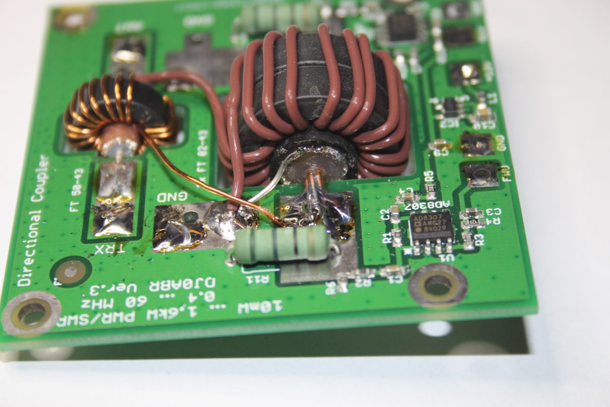
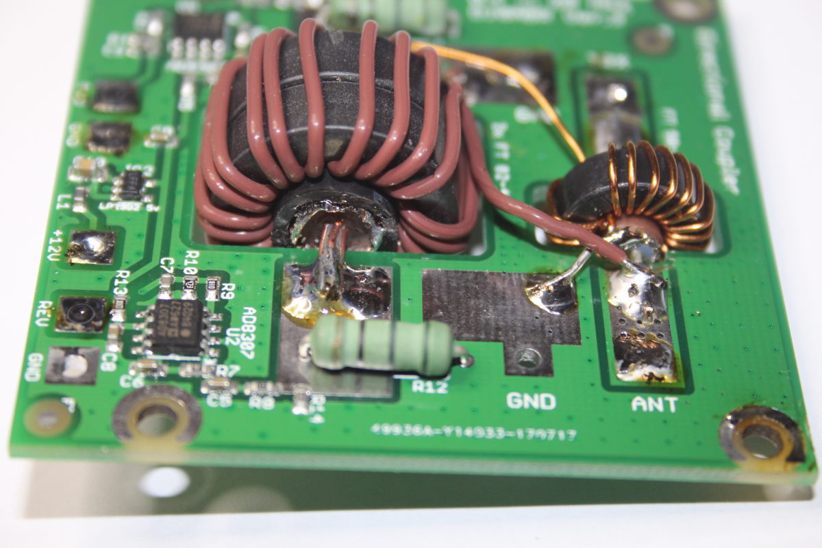
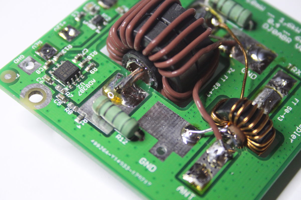
Connection of the ring cores:
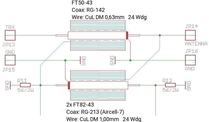
At
the top, ring core 1 is located directly between transmitter and antenna, which
measures the current through the antenna cable.
The
lower core is ring core-2, it measures the voltage at the antenna connection.
Together with the 50 Ohm resistors, they form the measuring bridge. The AD8307 is connected to the two decoupling lines.
56 Ohm resistors are used. Together with the input resistor of the AD8307 circuit, the required 50 ohm is obtained. An adjustment to 50 ohms would be possible, but in practice it can not be carried out because the accuracy of the usual measuring devices is not enough. A directional sharpness of better than 30dB can be achieved without any adjustment always and thus a SWR resolution of a few Hunderstel!
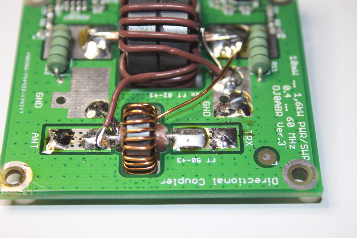
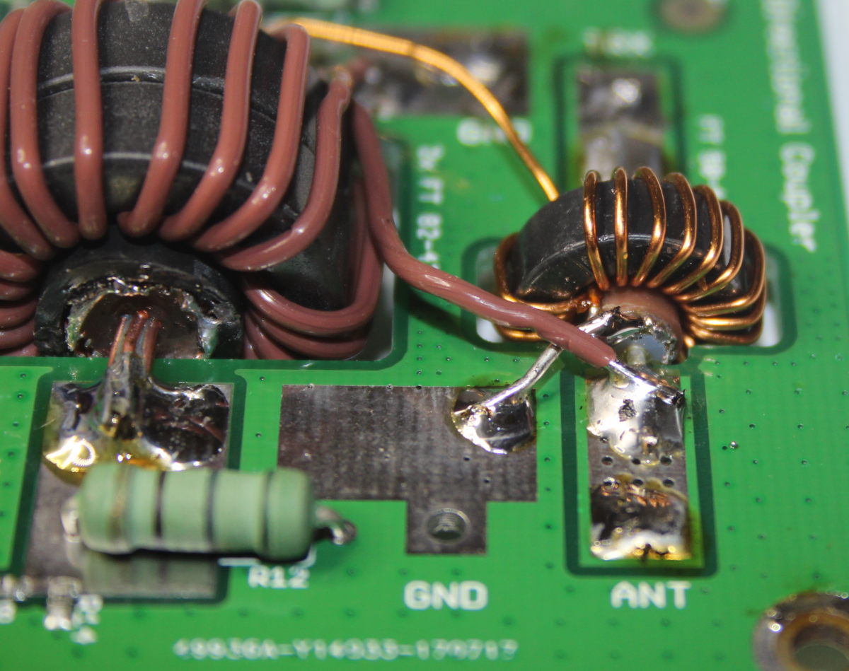
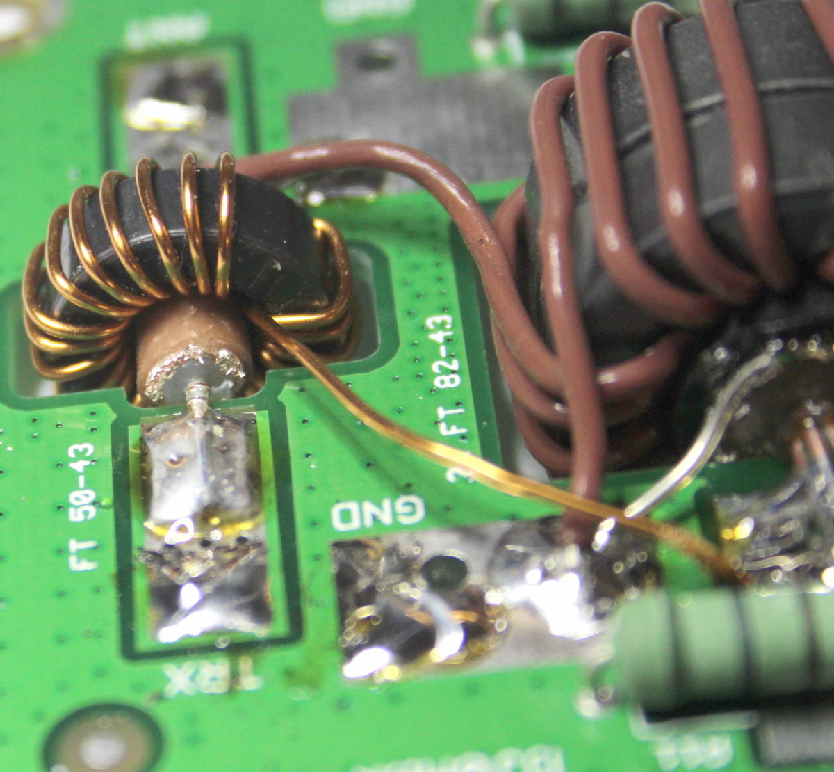
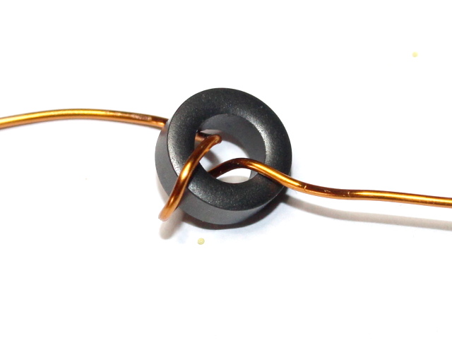
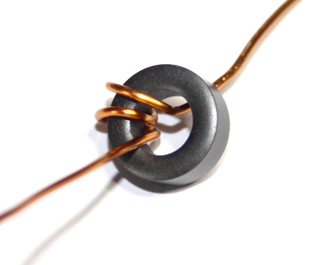
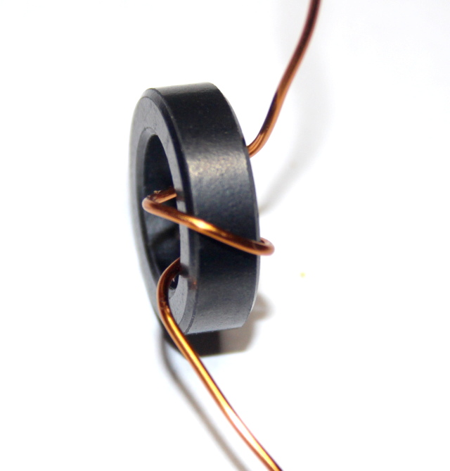
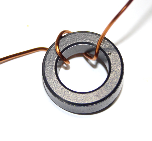
Winding scheme in detail:
There is no more confusing than the correct wrapping scheme. But that must be true. The layout is set to this wrapping scheme, one makes it wrong then one loses 10dB directional sharpness quickly.
To keep an overview, here is a photo gallery with detailed pictures. The point here is only to show in which direction the nuclei are being wound. On closer inspection, it can be seen that the cores FT50 and FT82 have opposite winding direction.
Winding number: 24 (for both nuclei)
Wire:
The FT50-43 is wound with CuL 0.63mm diameter (any wire between 0.35 and 0.65mm can be used)
The two bonded FT82-43 are wound with CuL 1.0mm diameter (any wire between 0.60 and 1.2mm can be used)
In the pictures the FT82-43 is tiled with teflon wire 0.34qmm (1mm outer diameter). This is easier than with CuL wire, since there is no danger of scratching the lacquer of the wire ( available here ).
Only the small FT50-43:
Then the scheme for the pair FT82-43:
Of course a FT82-43 double pack, here for a better overview the winding scheme on a single core.
AD8307 Measuring circuit:
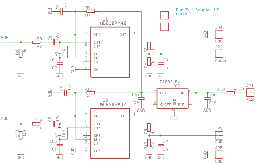
The 1.8 kOhm resistor is parallel to the 56 Ohm resistor (circuit diagram above), together with R8 and the input resistor of the AD8307 is reached to 50 Ohm.
At the solder terminals JP2 and JP3, a voltage corresponding to the leading and trailing power is outputted. This voltage is in the range of 0.5 to 2 volts and therefore fits the various display boards (see HERE and HERE ).
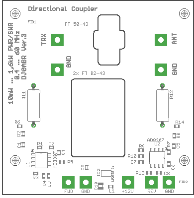
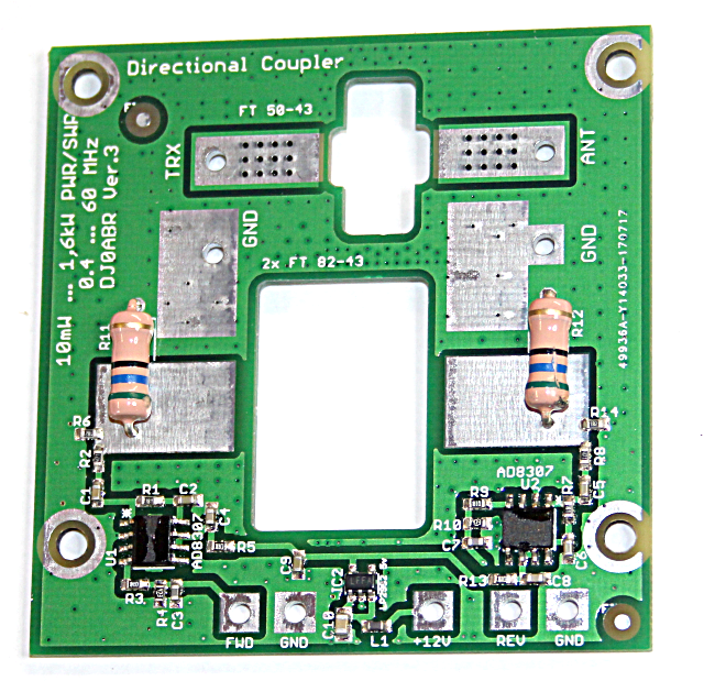
Board and placement plan:
The two cutouts serve to receive the ring cores.
Assembly instructions:
The finished board looks like this, without ring cores:
Preparation of the ring cores:
24 turns of CuL (approx.) DM 0.35 mm are wound onto the FT50-43. Wire diameters from 0.3 to 0.65mm can be used.
Two FT82-43s are glued together and then wound with 24 watt CuL (approx.) DM 0.63 mm, here wire diameters of 0.6 to 1.0 mm fit.
For better shielding (the coupler can only be used on 6m and 4m), the cables must be coaxial cables. However, in order to avoid short-circuiting the voltage to be measured, the shield of this coax cable may be connected to ground only on one side.
Prepare the following small cables:
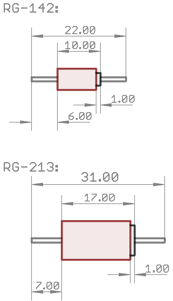
The cable is cut off flush to the inner conductor. On the right, 1mm of the screen remains, the ground is then connected.
This is how the RG-142 (alternatively RG-316) cable piece looks like:
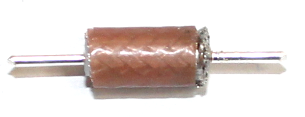
And here it is pushed by the FT50-43:
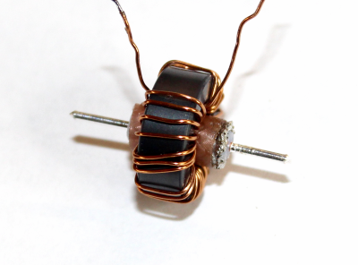
And the RG-213 (alternatively Aircell-7) Cable:
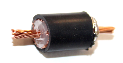
Details of the installation of the cores and their connection:
At the end of this article are several detailed photos. Please connect the cores exactly afterwards.
Check the coupler:
This coupler does not need any adjustment because the measurement is performed by the AD8307 which are very accurate. Of course, the coupler has a specific pitch ratio which is predetermined by the selected resistors. This ratio as well as always existing component tolerances are carried out by the display boards by software.
What we do to check the circuit board is to measure the directional sharpness because we want to be better than 30dB:
This is connected
The requirements for the dummy load are high, it should be in the range of 49.5 to 50.5 ohms. Usually, dummyloads are not as accurate, which is why we will measure poorer directivity than the coupler actually provides. If you want to know exactly, you need to measure 50 Ohm resistors precisely and also know the accuracy of the ohmmeter.
In order to measure the directional sharpness, we proceed as follows:
When you measure the three voltages, you enter them into this Excel sheet and you can read the directional sharpness. Yellow lines are to be entered, the others are calculated.
7 MHz we use, because KW dummyloads at higher frequencies always become inaccurate. If you use a 50 Ohm rf resistor is better off, but also here the accuracy measure. Furthermore, the dummyload has to be connected shortly, with a good coax cable and no adapter plug can be used because all this makes the directional sharpness look worse than it is.
Note on the measurement setup:
If the directivity of a coupler is exactly determined, the following prerequisites must be met:
*
Solder a 50 Ohm HF resistor directly and without cables to the output pins of
the board (cable and connectors already have a SWR of> 1,05 and therefore
would falsify the measured value)
*
Measure the 50 Ohm RF resistance (there are many resistances which have high
tolerances), it should deviate a maximum of 0.5 Ohm, but the directional
sharpness is not pressed on any 40dB. Observe
the tolerance of the resistance measuring device.
* Do
not hold any probes or other measuring devices as their capacitance will reduce
the measurement of the directional sharpness
* If
you want to measure the power at the same time, you can build a customized
output as described in the following link
On the subject of measuring accuracy I wrote my own article .
Detailed pictures: