Overview
The board DSP-7 can be used as a controller for ham radio power amplifiers (low bands, short wave, VHF/UHF/SHF) and also as a display for power/SWR meters (simultaneous single, dual or triple swr bridges).
This document focuses on the DSP-7 used as power amplifier controller. It supports most home brew amplifiers and turns it into a professional product.
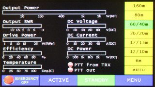
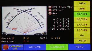
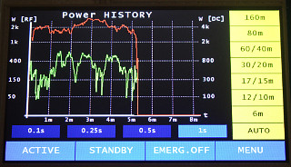
these are just three samples out of the 14 screen menus:
| Overview | Photo realistic | History |
|
|
|
User Interface: presentation of Power/SWR measurement
| Big 7" TFT color touch screen with SD card slot | |
| many convenient screens present measured values and amplifier status | |
| colored bar graphs and numbers | |
| photo realistic power/swr meter simulation | |
| history diagram, selectable recording times | |
| simultaneous power and SWR measured at the input, between amp and LPF and at the output | |
| works with any AD8307 based power/swr bridges by software calibration |
User Interface: analog measurements
| temperature-1: temperature of the power transistor | |
| temperature-2: temperature of the heat sink | |
| supply voltage (four selectable ranges from 50V to 4kV) | |
| supply current (four selectable ranges from 10A to 200A) | |
| frequency measurement | |
| DC input power | |
| amplifier efficiency |
User Interface: amplifier control
| ON switch: by touch button or external button | |
| STANDBY: by touch button or external button | |
| ACTIVE: by touch button or external button | |
| Emergency OFF: by touch button or external button |
Switching functions:
| PTT controller | |
| BIAS on/off (disables the amp's bias voltage in case of errors) | |
| fan or water pump control | |
| DC power supply control | |
| security circuit control | |
| ALC, monitors current consumption to limit drive power, thus is independent from SWR |
Band and antenna selection:
| band selection via touch button or external rotary switch | |
| automatic selection of up to 3 antennas, comfortable assignment of bands to antennas | |
| automatic band and antenna selection for ICOM transceivers |
Security functions:
| Monitoring of the supply voltage, total shutdown in case of error | |
| Monitoring of the supply current, total shutdown in case of error | |
| Temperature measurement: automatic fan on/off and disabling TX if exceeding an adjustable limit | |
| controlling the transceiver via ALC to reduce drive power | |
| monitoring the drive power and switching into standby if limit is exceeded | |
| monitoring of the SWR between amplifier and low pass filter, shutdown in case of wrong filter selection | |
| monitoring of antenna SWR. If worse than 2:1 switching into RX mode, if worse than 3:1 emergency shutoff |
WiFi:
| Integrated WiFi interface | |
| AP (access point) mode | |
| client mode | |
| integrated web server | |
| presentation of measured values and amplifier status | |
| can be viewed by a web browser on PCs and smartphones |
Miscellaneous:
| serial CI/V interface for future extensions | |
| RS232 interface for firmware updates | |
| users can update many pictures by own graphics with an SD card | |
| powerful ARM Cortex 3/4 micocontroller with 1MB flash | |
| DC supply: 10-15 volts, 250mA | |
| controller and display is one compact unit, easy mounting to front panels | |
| RF tested 4-layer PCB, inputs with EMI ferrites and capacitors | |
| individual full size ground plane | |
| individual power supply planes |
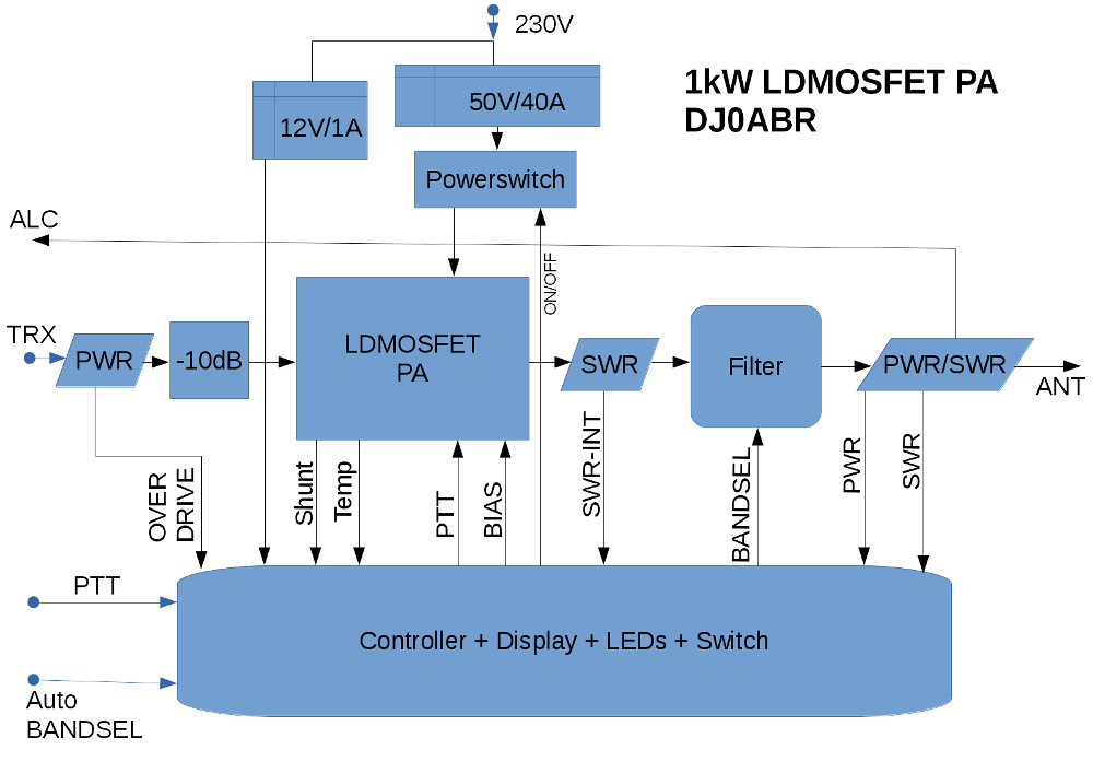
Block diagram of a complete amplifier using this controller: