Overview
To use a powerful amplifier in our Shack we need a controller which handles the operation and checks various parameters in real time. We need RX/TX control, supervision of the current consumption, power and SWR and many other security features. Then we can concentrate on our QSOs and don't need to handle the amplifier manually.
NEW boards avalable: see HERE.
Overview:
This totally new developed controller board has a huge number of digital and analog inputs and outputs for switches, LEDs, sensors, safety circuits and a TFT-Color display with touch operation. Additionally this controller has 19 LEDs to show the operating status of the amplifier. This controller is now available for everybody, worldwide as a single PCB or as a fully assembled and tested board (see link above).
Up to three Power/SWR bridges may be connected. These bridges must be based on the well known AD8307. These boards are also available, but any other AD8307 board may also be used because the software has a calibration menu. As a minimum one Power/SWR bridge is needed for the antenna output. Optionally a second one can be connected between the amplifier and the low pass filter to detect wrong filter settings, and a third bridge may be connected to the RF input to detect too high input power (alternatively or additionally you can use also the ALC circuit).
Functional overview:
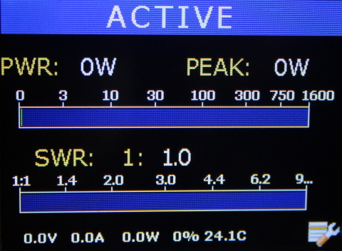
| Shows all measured values in the color display, either as numbers or as horizontal bar or both | |
| power, SWR | |
| current, voltage | |
| efficiency | |
| temperature | |
| supervision of all measured values | |
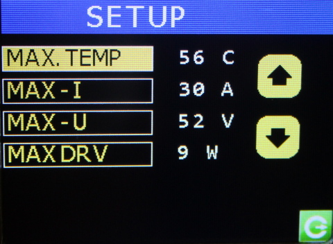
| emergency shutdown if (adjustable) limits are exceeded | |
| coordinating RX/TX switch | |
| multi stage emergency program selects deactivation up to total shutoff | |
| fan control | |
| pump control in case of water cooling | |
| ALC, monitors current consumption to limit drive power, thus is independent from SWR |
Security functions:
| Monitoring of the supply voltage, total shutdown in case of error | |
| Monitoring of the supply current, total shutdown in case of error | |
| Temperature measurement: automatic fan on/off and disabling TX if exceeding an adjustable limit | |
| controlling the transceiver via ALC to reduce drive power | |
| monitoring the drive power and switching into standby if limit is exceeded | |
| monitoring of the SWR between amplifier and low pass filter, shutdown in case of wring filter selection | |
| monitoring of antenna SWR. If worse than 2:1 switching into RX mode, if worse than 3:1 emergency shutoff |
Block diagram:
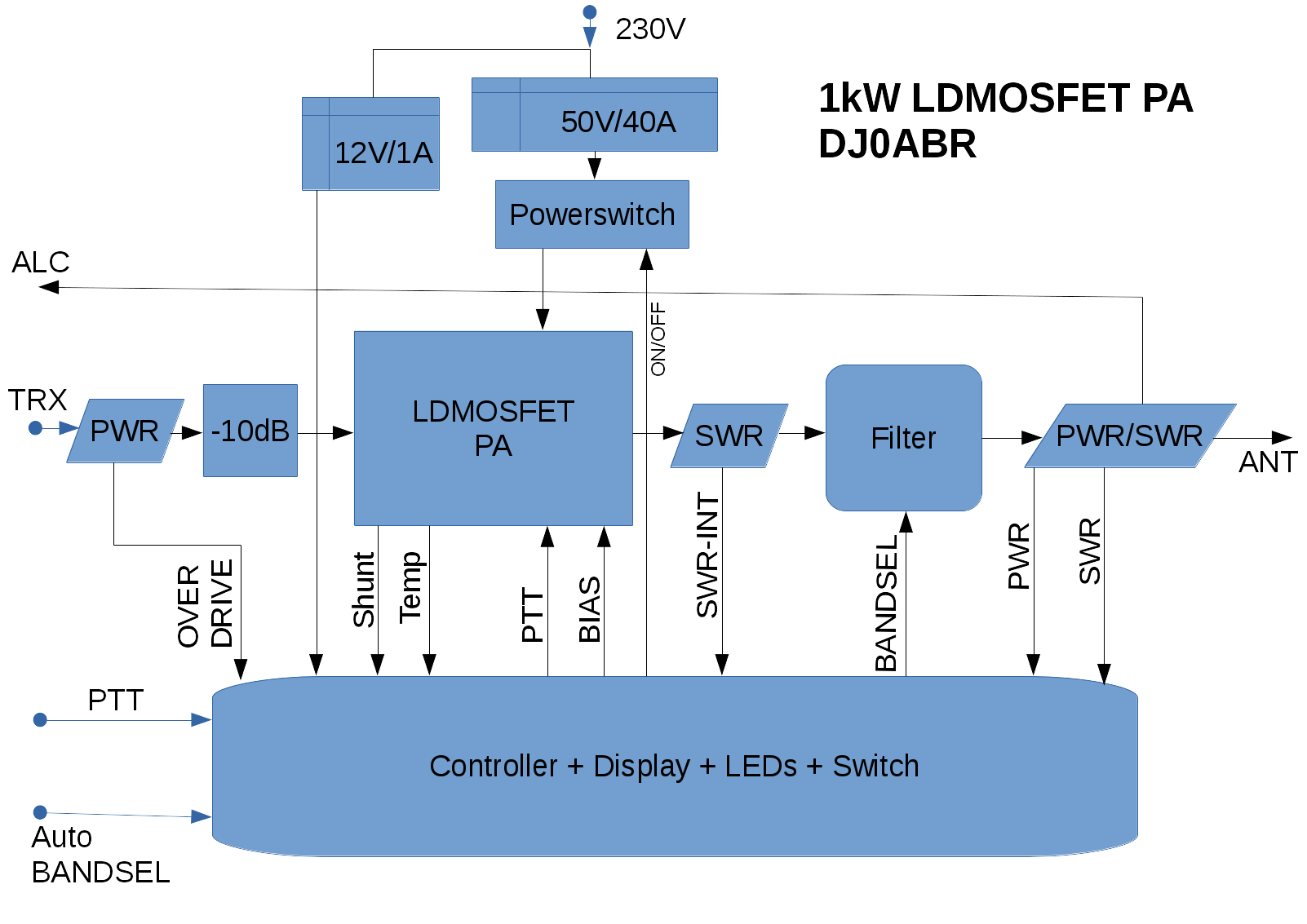
Overview of the Connections:
Analog Inputs:
- Input power (Drive Power) from transceiverr
- Output power (at the antenna connector)
- SWR (at the antenna connector)
- SWR between amp and filter
- power supply voltage
- power supply current
- cooler temperature
- automatic band selection (in case of ICOM transceivers)
- various spare inputs for future extensions
Analog Outputs:
- ALC, negative ALC voltage to the transceiver
Switching Inputs:
- PTT from transceiver
- Push-Button: On
- Push-Button: Off
- Push-Button: Standby/Active
- 8-pos rotary switch for manual band selection
- various spare inputs for future extensions
Switching Outputs:
- TX/RX Relais
- BIAS on/off (switching the bias voltage of the MOSFETS)
- outputs to control the low pass filters
- TFT lighting on/off
- fan (pump) on/off
- mains power relais on/off
- various spare outputs for future extensions
Controls:
- TFT Color display 3,2" with touch function
- Rotary switch for band selection
- three push-buttons for ON/OFF/STANDBY
LEDs:
- On/Off
- TX
- 160m
- 80m
- 60+40m
- 30+20m
- 17+15m
- 12+10m
- Automatic band selection (Icom)
- Temperature (2 LEDs)
- output SWR (2 LEDs)
- filter SWR (2 LEDs)
- power supply voltage (2 LEDs)
- current consumption (2 LEDs)
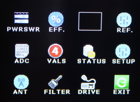
Example of some screens: