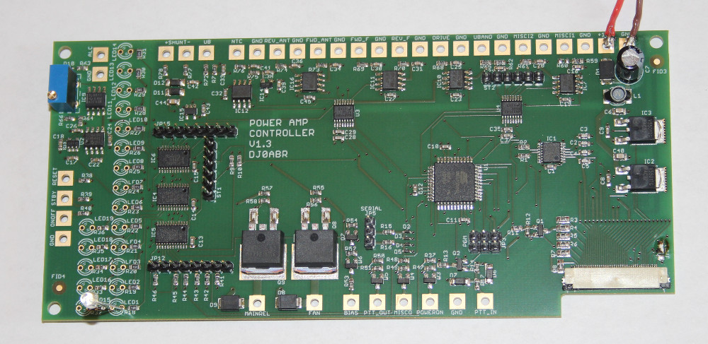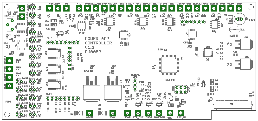
the PCB
Many connections are done with thin coaxial cables (i.e. RG312 or similar), so the pads are big and located at the PCB's edges.
19 LEDs are located right of the display (the pictures here show the back side). The LEDs are in a good distance from the display to make the front panel looking nice.
The longer LED row is in green color and is used to show operating conditions. The 5 LEDs in the other row are in red color and show emergency situations.
The trimmer in the top left is used to adjust the current consumption of the amplifier where the ALC is activated to reduce the drive power.
Two bigger Mosfet transistors are used to drive an external power relais and the fan.