User Manual
First of all, let's have a look at the normal QSO operation:
12V-power ON:
By switching ON the 12V supply the controller gets active but stays in a silent idle mode. The display is switched off. The ON LED flashes every 3 seconds to show this idle mode. The only active process is the temperature measurement and the FAN control.
Switch ON:
To activate the controller push the button "ON" which is connected to the ONOFF solder pad and ground.
The display will be activated and shows one of the selected menus. The output pad MAINREL will be activated (connected to ground) and can be used to switch a relais to activate the power supply of the amplifier.
The controller shows "STANDBY", thus the amplifier cannot be activated by pressing the PTT. Instead the transceiver is directly connected to the antenna. This allows to check the antenna before activating the amp..
ACTIVE / STANDBY:
To activate the controller push the button "ACTIVE/STANDBY" which is connected to the STANDBY solder pad and ground.
The display shows ACTIVE and the amp will go to TX mode if the PTT is pushed..
Switch OFF:
To deactivate the controller push the button "OFF" which is connected to the RESET solder pad and ground.
The display and all other functions are switched off. The temperature measurement and fan control are the only functions still operational (of course, the controller's 12V supply must still be switched on).
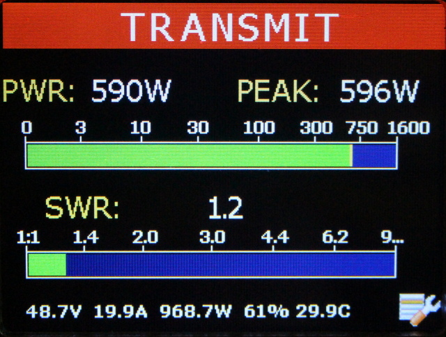
this is the screen menu which is usually used:
the most important data are shownt:
| RF power | |
| peak power (10.000 measures per second !) | |
| SWR |
and in the bottom line:
DC voltage, DC current, DC powerm effectivity, temperature.
Change menus:
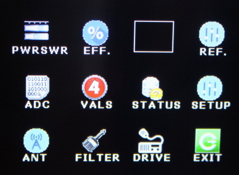
pressing the tool-button in the right bottom corner will show the menu selection screen:
PWRSWR ... usual used menu, see above
EFF ... Shows the amp's effectivity
REF ... Input menu for the reference values of the Pwr/Swr bridges
ADC ... shows all analog input values in raw mV format
VALS ... like ADC, but the values are the calculated real values.
STATUS ... status of the controller and the inputs and outpts
SETUP ... set the security limits in this menu
ANT ... shows detailed data of the Pwr/Swr bridge at the antenna output
FILTER ... shows detailed data of the Pwr/Swr bridge between amp and filter (if installed)
ANT ... shows detailed data of the Pwr/Swr bridge at the amps input (if installed)
EXIT ... returns to the previous screen
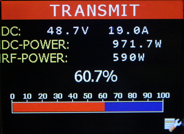
Efficiency:
choose this screen to show details about the amplifier's efficiency which is the relation between DC power and RF power.
the efficiency depends i.e. from the quality of the low pass filter. Using this screen you can detect bad or ineffective filters.
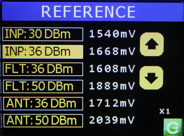
REFERENCE settings:
you can connect any possible Pwr/Swr bridges if they are based on the AD8307. This screen is used to calibrate the controller to your Pwr/Swr bridge.
The calibration is done using two measurement points, the first at 4 watts (36 dBm) and the second at 100 watts (50 dBm)RF ouitput power..
- enter the REF screen menu
- set your transceiver to a power output of 4 watts
- measure the output voltage of the "forward" port of your AD8307 bridge.
- enter this value.
do the same at a power of 100 watts. Choose a setting by touching the yellow line. If you touch the same line again the digit changes (x1, x10 oder x100). Enter the value with the arrow buttons. To measure this reference value in mV you can use any voltmeter, but it is more precise to do the measurement with the ADC screen which also shows this mV value.
Do the same procedure for the other Pwr/Swr bridges (if installed). The input-bridge is calibrated at lower levels (1watts and 4 watts).
all settings are permanently stored in an onboard EEPROM..
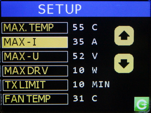
SETUP:
use the SETUP menu to enter the limits for the security functions:
MAX.TEMP ... if the temperature is above MAX.TEMP then the transmission will be terminated and the amp switches into standby mode. Then the transceiver is directly connected to the antenna.
MAX-I ... if the DC current is higher than MAX-I then the controller does an emergency shutdown and deactivates everything.
MAX-U ... if the DC voltage is higher than MAX-U then the controller does an emergency shutdown and deactivates everything.
MAX DRV ... if the drive power is higher than MAX DRV then the controller does an emergency shutdown and deactivates everything. Use the ALC function to avoid this situation.
TX LIMIT ... maximum TX time. If the amplifier is transmitting longer than TX LIMIT it will return to STANDBY. Then the transceiver is directly connected to the antenna.
FAN TEMP ... the FAN output will be activated at this temperature, and will be deactivated at a temperature of 3 degC below.
other emergency situations and recovering from an emergency shutdown:
an antenne SWR of > 3:1 will also cause an emergency shutdown.
To recover from an emergency shutdown press the OFF button and the ON button.
Menu: ADC:
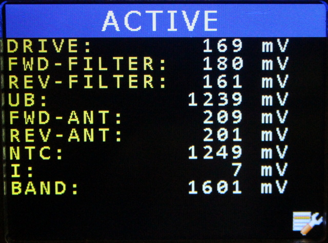
This controller has 16 analog inputs, 9 are actually used ad 7 reserve. The ADC screen shows the voltage in mV directly at the ADC inputs. This value can i.e. be used to calibrate the Pwr/Swr measurement (see REF menu).
Menu: VAL:
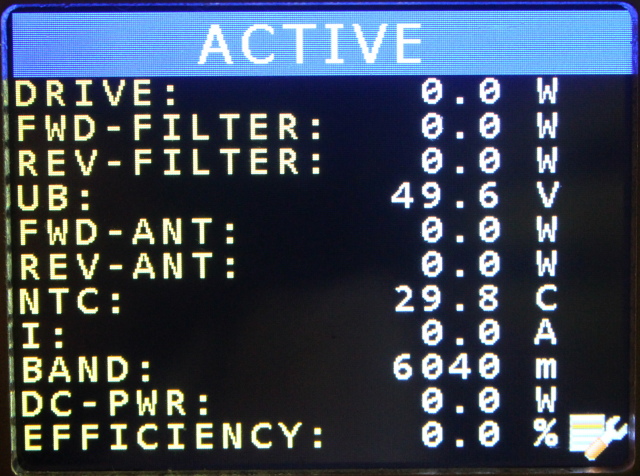
as above, but the real values are calculated.
Menu: STATUS:
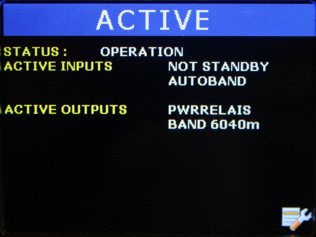
shows the actual status of the controller and it's input and output lines. I.e.: you can check if the FAN output is activated etc.
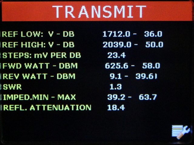
Menu: ANT, FILTER, DRIVE:
these three menus (all equal) show details about the Pwr/Swr bridges:
REF LOW / REF HIGH ... the calibration values (mV at the power dBm)
Steps in mV per DB ... a calculated value
FWD WATT - DBM ... the real forward power in watts and dBm
REV WATT - DBM ... the real reverse power in watts and dBm
SWR ... the calculated SWR
IMPED.MIN-MAX ... the antenna can have one of these two values (the pictures shows that my old dummy load has 63,7 ohms instead of 50 ohms).
REFL. ATT ... the reflection attenuation in dB calculated from the SWRhm liegt verursacht werden. Diese Messbrücken können nicht feststellen ob der Antennenwiderstand über oder 50 Ohm liegt, daher werden beide möglichen Werte ausgedruckt.
The DRIVE menu shows (if installled) only some values because the reverse power is not used.