Measurement Results
The filters are calculated as good as required, but not as good as possible, to get a low insertion loss.
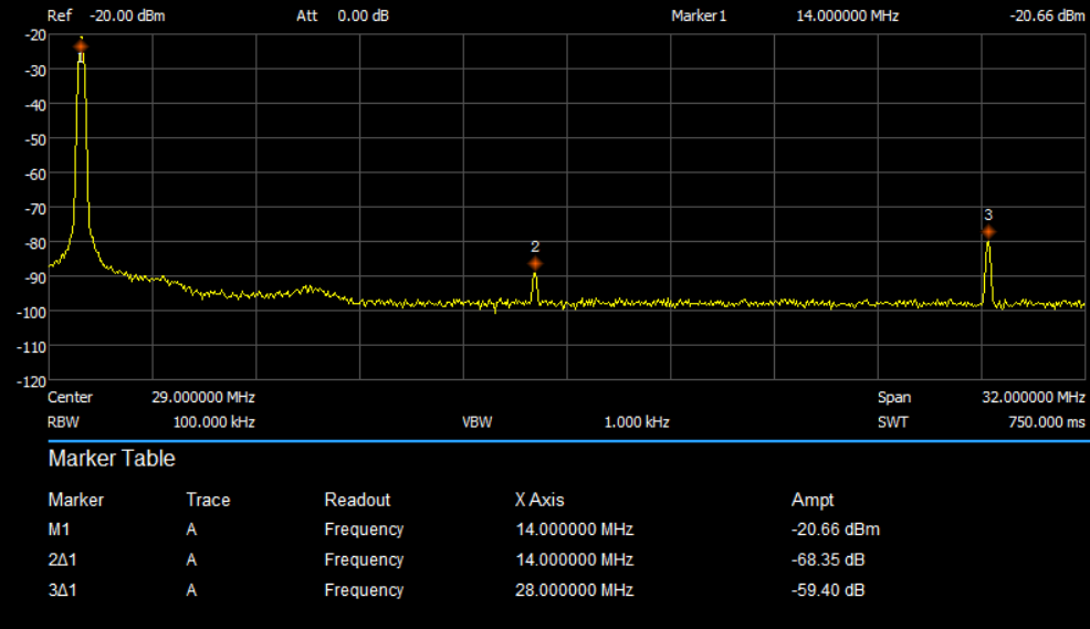
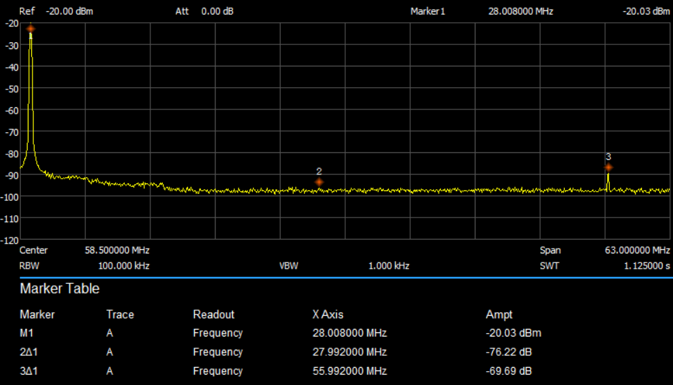
The big challenge is the 30m band which uses the 20m band filter. Luckily the second harmonic of LDMOS amps is low which helps a lot.
Testing under load:
* Connection of a good 1kW dummyload
* send 1kW on each band for at least one minute in FM mode (continues power)
* Measure the temperature of the filter componentsAll filters had 40 degC max, only the 15m filter had 48 degC. For normal operation we don't need any cooling. For long FM transmissions a little cooling can help. The filter should not get over 50 degC.
Measurement Setup:
Transmitter: IC-7300 (abt. 4 watt output)
Amplifier: the LDMOS amp described here
Power at the antenne 1kW
1kW Dummyload 50 Ohm (cooled by a fan)Connected to a Siglent analyser via a 50 ohms attenuator at the dummy load.
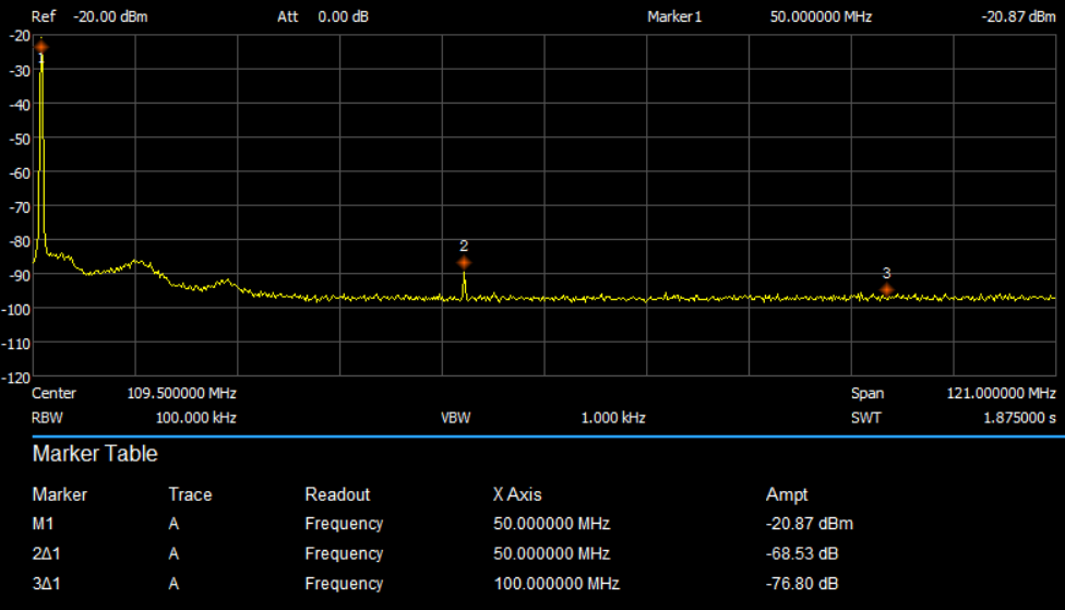
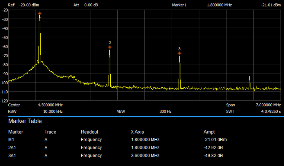
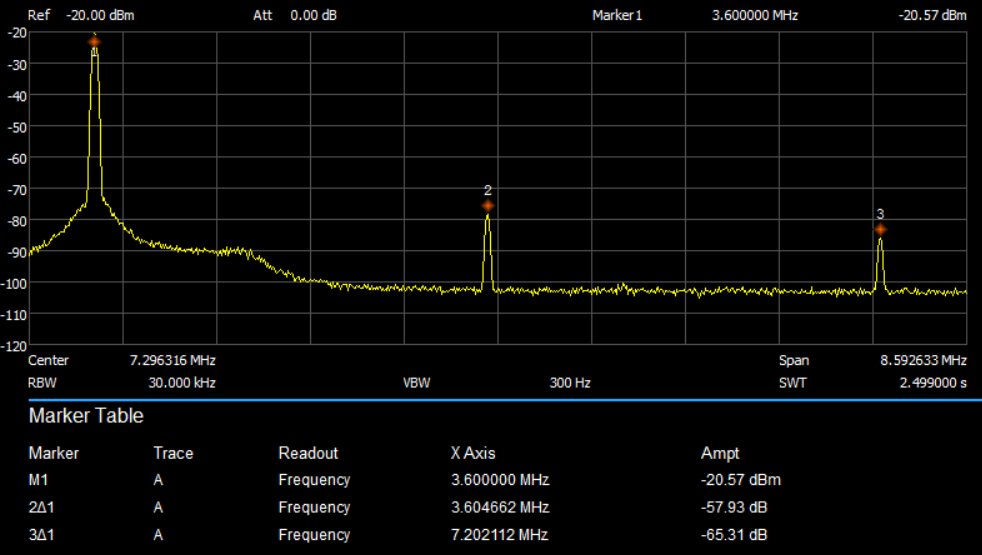
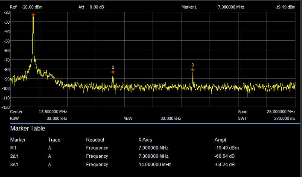
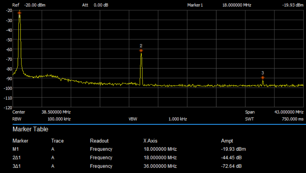
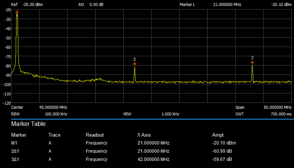
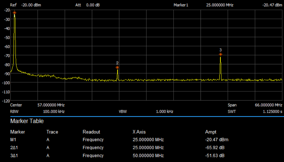
In these measurements the carrier is set to -20dBm using an attenuator between dummyload and analyser. The second and third harmonic is shown as the difference to the carrier dBc.
M1 ... carrier
2Delta1 ... level of the second harmonic compared with the carrier
3Delta1 ... level of the third harmonic compared with the carrier
Always keep in mind: a low insertion loss is more important than the attenuation of the harmonics (as long as the attenuation fulfils the legal requirements).
Ausgangsspektrum auf dem 160m Band
Ausgangsspektrum auf dem 80m Band
Ausgangsspektrum auf dem 60m Band
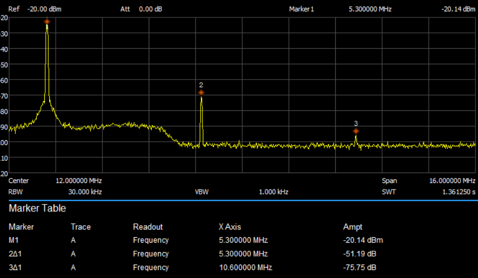
Ausgangsspektrum auf dem 40m Band
Ausgangsspektrum auf dem 30m Band
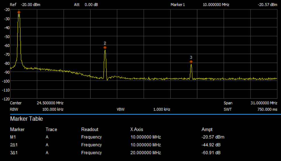
Ausgangsspektrum auf dem 20m Band
Ausgangsspektrum auf dem 17m Band
Ausgangsspektrum auf dem 15m Band
Ausgangsspektrum auf dem 12m Band
Ausgangsspektrum auf dem 10m Band
Ausgangsspektrum auf dem 6m Band