Bill of material:
4 pcs. enammelled copper wire (CuL) diameter 2.0mm, length 0.5m each.
6 pcs. 47 pF 3kV SMD 1812 capacitor
9 pcs. 22 pF 3kV SMD 1812 capacitor
2 pcs. 15 pF 3kV SMD 1812 capacitor
2 pcs. 10 pF 3kV SMD 1812 capacitor
L6 and L19, air coils:
The inner diameter of this coil is 17mm, the real diameter 19mm and the outer diameter 21mm.
Wind 7 turns and strech the coil to a length of 20mm. The resulting air coil will have an inductance of 0.62uH. Check with an LC meter, the tolerance is 0.6 to 0.64 uH. If required, strech or compress the windings. If you have an spectrum analyser you will need a tuning range from 0.6 to 0.68uH for fine tuning. Otherwise use 0.62uH.
L5 and L8, air coils:
The inner diameter of this coil is 17mm, the real diameter 19mm and the outer diameter 21mm.
Wind 5 turns and strech the coil to a length of 15mm. The resulting air coil will have an inductance of 0.32uH. Check with an LC meter, the tolerance is 0.3 to 0.35 uH. If required, strech or compress the windings (usually it is required). If you have an spectrum analyser you will need a tuning range from 0.3 to 0.4uH for fine tuning. Otherwise use 0.32uH.
47pF ... C92,93,89,88,98,99
22pF ... C95,94,90,4,5,6,101,100,96
15pF ... C86,87
10pF ... C91,97
With higher frequencies ist gets hard to match simulation and reality. Therefore I will not show the simulation above 10 MHz. Here are the real measured values from the fine tuned filter using above values:
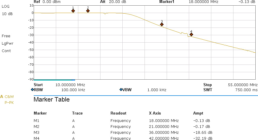
The passband attenuation of -0.13 (-0.17)dB is a good value at these frequencies and shows that copper wire is still OK instead of the expensive silver wire. When transmitting with 1kW we have a loss of only 30 (39) watts.
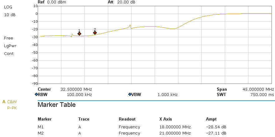
This is the reflection attenuation. -27 dB corresponds to an SWR of 1,09 : 1. When transmitting with 1kW a power of 2 watts will be reflected back to the amp. These 2 watts are already included in above 30 watts and are therefore not relevant and do not need any tuning.
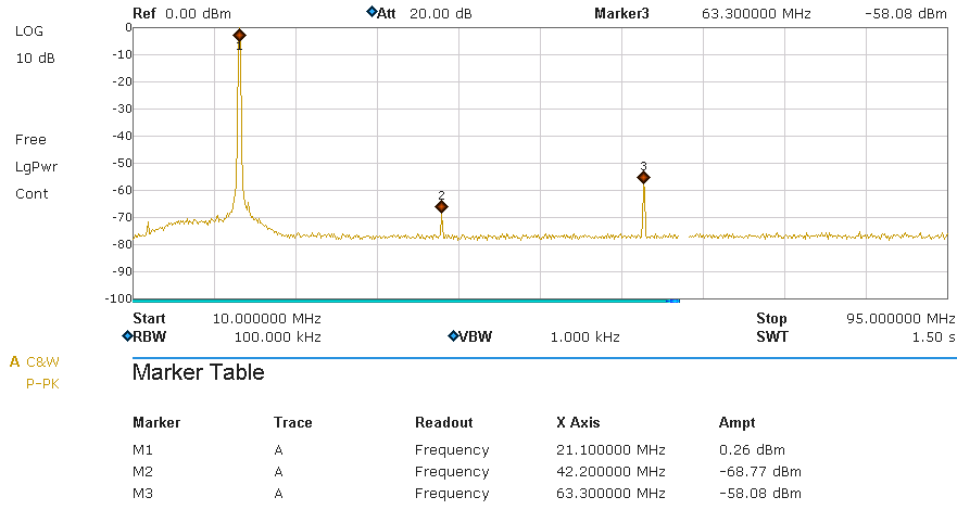
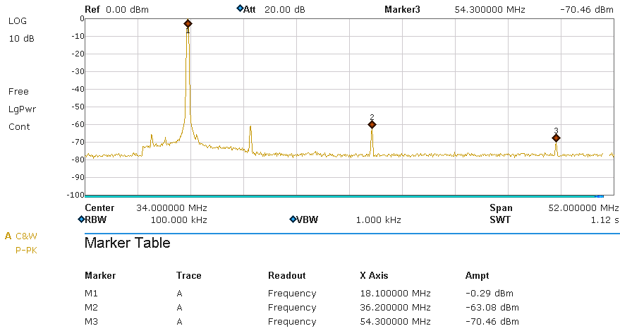
Results:
this picture shows the spectrum on a 50 ohms dummy load. The filter was driven by a Helitron.de LDMOS amplifier running at 1kW output power. A HP-attenuator was used to adjust the output to about 0 dB (The value at marker M1 is NOT the passband attenuation, its just the 0-reference for this graph). The readings for the harmonics are the filter attenuation. The legal limit is -40dB (BNetzA 33/2007) and in USA (FCC 97.307) -43 dB. This requrement is fulfilled.
17m:
15m: