L4 and L9, air coils, CuL diameter abt. 2.0mm
The inner diameter of this coil is 19mm, the real diameter therefore 21mm and the outer diameter 23mm.
Wind 5 turns and strech the coil to a length of 20mm. The resulting air coil will have an inductance of 0,43uH. Check with an LC meter, the tolerance is 0,41 to 0,45 uH. If required, strech or compress the windings on the core.
All capacitors are 47 pF:
C6 - C11 ... 47 pF
C12 - C17 ... 47 pF
C7,8,9,102,103,104,105 ... 47 pF
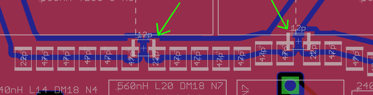
CE1, CE2 ... 10pF (see text at the end of this page)
With higher frequencies ist gets hard to match simulation and reality. Therefore I will not show the simulation above 10 MHz. Here are the real measured values from the fine tuned filter using above values:
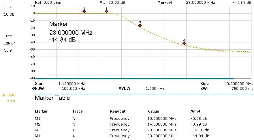
An spectrum analyser (except the very expensive ones) is not the ideal tool to measure the attenuation in hundreds of a dB. Therefore I did this measurement with a generator and an RF power meter again. The passband attenuation on 14 MHz is -0,18 dB (not -0,29 dB as shown in the graph). The attenuation for the first harmonic of the 30m band is -19 dB, together with the attenuation of the LDMOS amplifier itself we get the required -40dB or better (my amp has -29 dB already, plus 16 dB results in -45dB for the first harmonic).
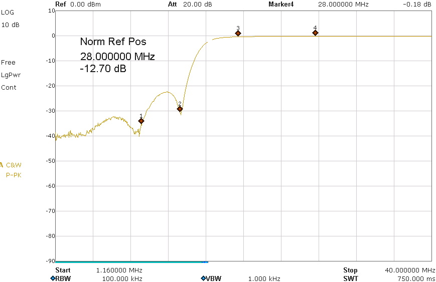
This is the reflection attenuation. -30dB is a good value, so the filter is very close to 50 ohms.
CE1, CE2:
It is hard to build a filter for 30m and 20m, because the first harmonic of the 30m band is at 20 MHz which is very close to 14 MHz. Without any additional action we would have only about -6dB attenuation. The solution is to give the filter a bit eliptical characteristic. This makes the curve steeper and the attenuation better without influencing the passband attenuation.
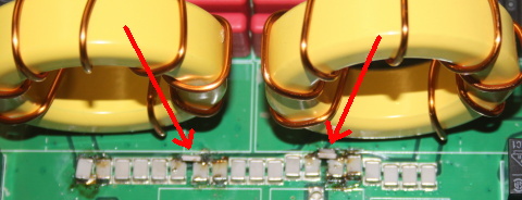
What we do is this:
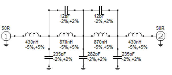
we add two 10pF capacitors in parallel to the inner cores (the exact value would be 12pF 3kV, but its hard to get them, so we use 10pF). This is not provided by the PCB layout, but thanks to SMD it is very easy to mount these caps:
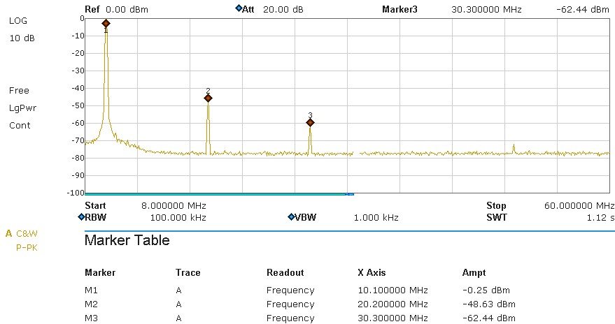
Results:
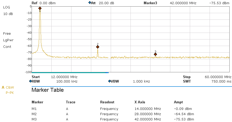
this picture shows the spectrum on a 50 ohms dummy load. The filter was driven by a Helitron.de LDMOS amplifier running at 1kW output power. A HP-attenuator was used to adjust the output to about 0 dB (The value at marker M1 is NOT the passband attenuation, its just the 0-reference for this graph). The readings for the harmonics are the filter attenuation. The legal limit is -40dB (BNetzA 33/2007) and in USA (FCC 97.307) -43 dB. This requrement is fulfilled on 30m as well as on 20m.
30m:
20m: