L17:
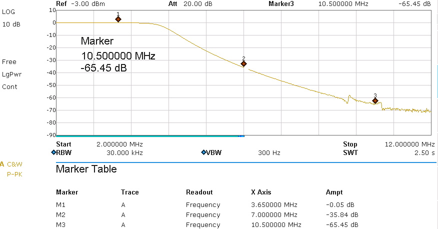
Wind 15 turns on the core. The inductance will be about 3.0 uH. Check with an LC meter, the tolerance is 2.9 to 3.1 uH. If required, strech or compress the windings on the core.
C14, C17 ... 1 nF
C35, C38 ... 1,5 nF
C15, C16 ... 3,3 nF
C36, C37... 2,2 nF
using these values the simulated attenuation looks like this:
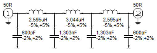
the red curve is the attenuation, the blue curve the reflection (5dB per hor. line). So the reflection is about -26dB. These are ideal values without any losses. Lets see what this filter really does on our PCB:
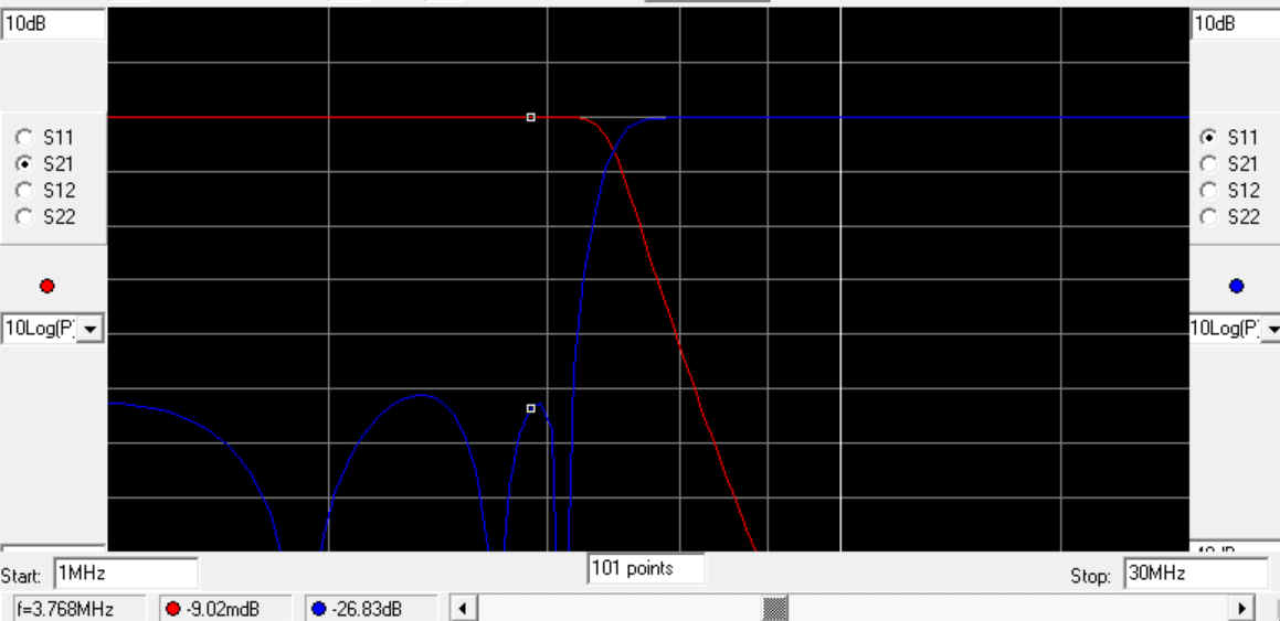
This is the attenuation in the 80m band, the passband attenuation with less than 0,1 dB is extremely good, so the filter will not get hot at high power. Together with the harmonics attenuation of the amplifier itself, the results are very good and much deeper than the limit of -40 dB.
The little hop around marker-3 is caused by crosstalk to other filters on the PCB. Since it is abt. 60dB below the carrier we can ignore it.
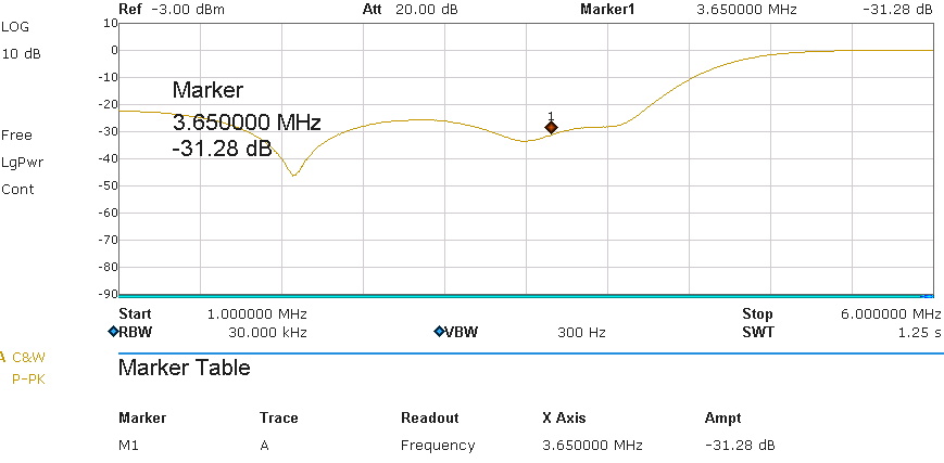
Finally the reflection attenuation was measured. This is the SWR at the filter input (and output, since the filter is symmetrical) and shows how close the filter input is matched to 50 ohms.
The reflection attenuation is -31 dB. Converted into the SWR this is an SWR at the filter input of 1,06 : 1. If we transmit 1kW then the filter input will reflect on 3.65 MHz a power of only 0,79 watts back to the amplifier. All harmonics will be reflected by almost 100%. These values are similar, or even better, compared with the simulation.
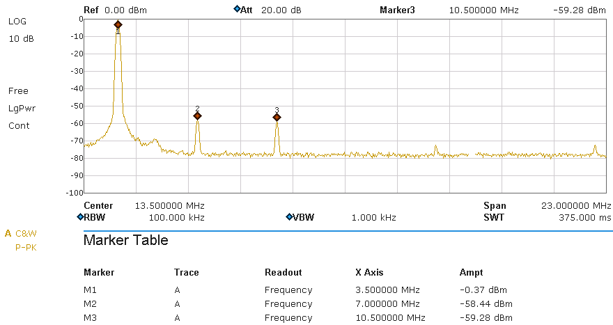
Results:
this picture shows the spectrum on a 50 ohms dummy load. The filter was driven by a Helitron.de LDMOS amplifier running at 1kW output power. A HP-attenuator was used to adjust the output to about 0 dB (The value at marker M1 is NOT the passband attenuation, its just the 0-reference for this graph). The readings for the harmonics are the filter attenuation. The legal limit is -40dB (BNetzA 33/2007) and in USA (FCC 97.307) -43 dB. This requrement is fulfilled.