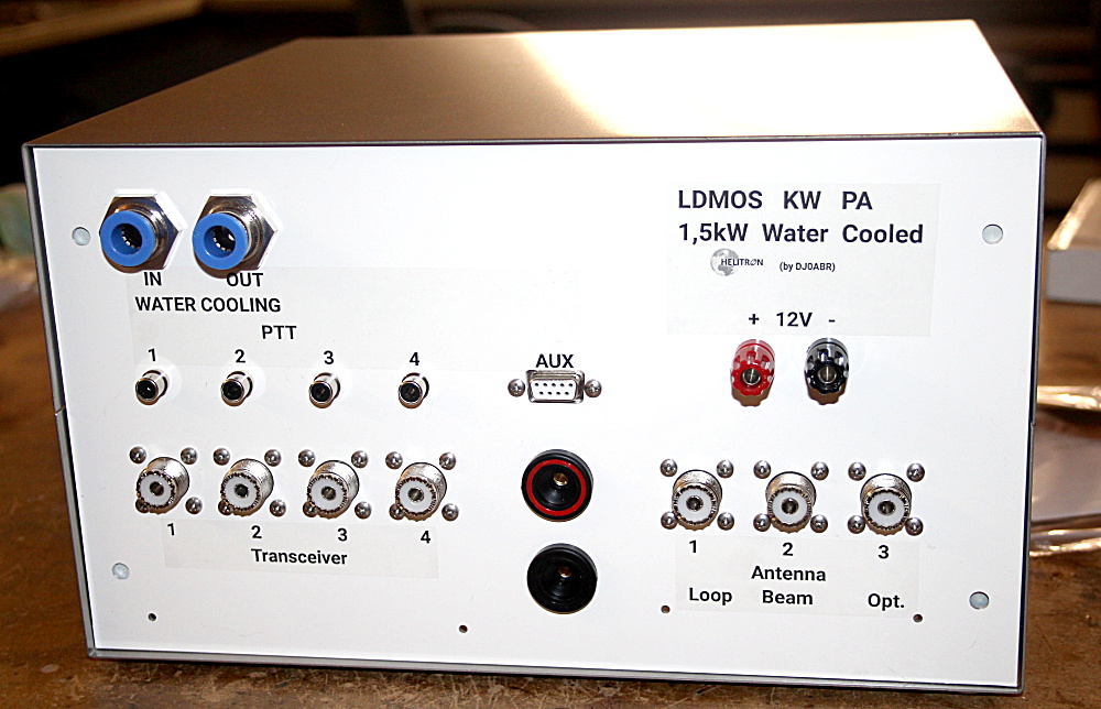
connects 4 transceivers to amplifiers or antennas
Connecting more than one transceiver to antennas and power/swr meters
leads to a terrible tangle of cables and connectors.
And if an additional amplifier is used the chaos in the shack is perfect.
To handle these problems two boards have been developed: the automatic input selector and the antenna output relais board.
This page describes the automatic input selector. The antenna output relais board is described HERE.
Overview:
This board has four RF-inputs (mechanically compatible to N or PL connectors) and four PTT inputs. And it has one output that can go to an antenna, amplifier, Power/SWR meter or antenna switch board.
The typical application is to connect up to four short wave transceivers to this board. As soon as the PTT is pushed at one transceiver the antenna will be automatically switched to this transceiver. And it stays there even if the power is switched off until the PTT is pushed at another transceiver.
Removing the need for cables and connectors is the highlight of this board: The transceiver connectors (N or PL connectors) can be directly soldered to this board. No need for any cabling inside of the switch box or amplifier. See this video
TX attenuator option: if this board is used as a transceiver selector in front of an amplifier the TX attenuator can be a useful option. Most transceivers have too much power to drive an amplifer. The TX attenuator lowers this power by 10dB (10:1) and makes it easier to drive i.e. LDMOS amplifiers. The TX attenuator is build from 35 watts resistors and has an RX/TX relais. It is inactive during reception.
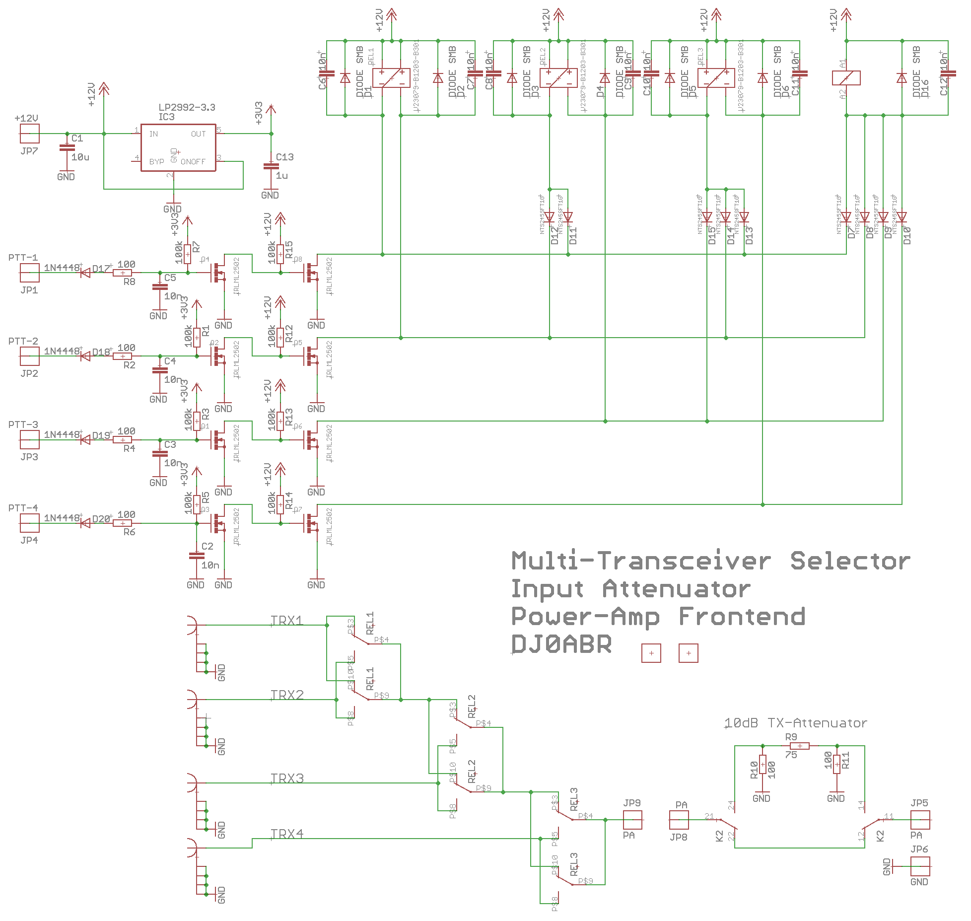
Schematic:
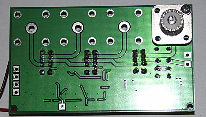
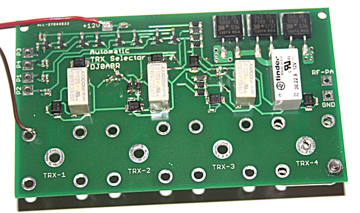
Circuit board:
Four N or PL connectors are mounted to the rear side of the box as usual. Then this board is directly solderd to these four connectors. This eliminates the need of four coaxial cables.
it used bi-stable relais, the switch stays at the current position even if the power is switched off. All switched lines are RF-decoupled by capacitors.
Connecton to the DSP-7 controller:
If you use this
transceiver selector together with the DSP-7 controller, the common PTT (which
is switched by all 4 transceivers) must be looped through to the DSP-7.
In addition, the RX / TX relay on the transceiver selector board must be
controlled by DSP-7.
The connection is made in 3 steps:
1. Disconnect the
trace marked with the yellow X, scrape through (only required for the
version with -10dB attenuator).
2. From
the 4 diodes, one wire goes to the DSP-7 connector "PTT in"
(always required).
3. the rx/tx relay
is controlled by the DSP-7 connection "PTT out". Make the wire
as shown in the picture
(only required for the version with -10dB attenuator).
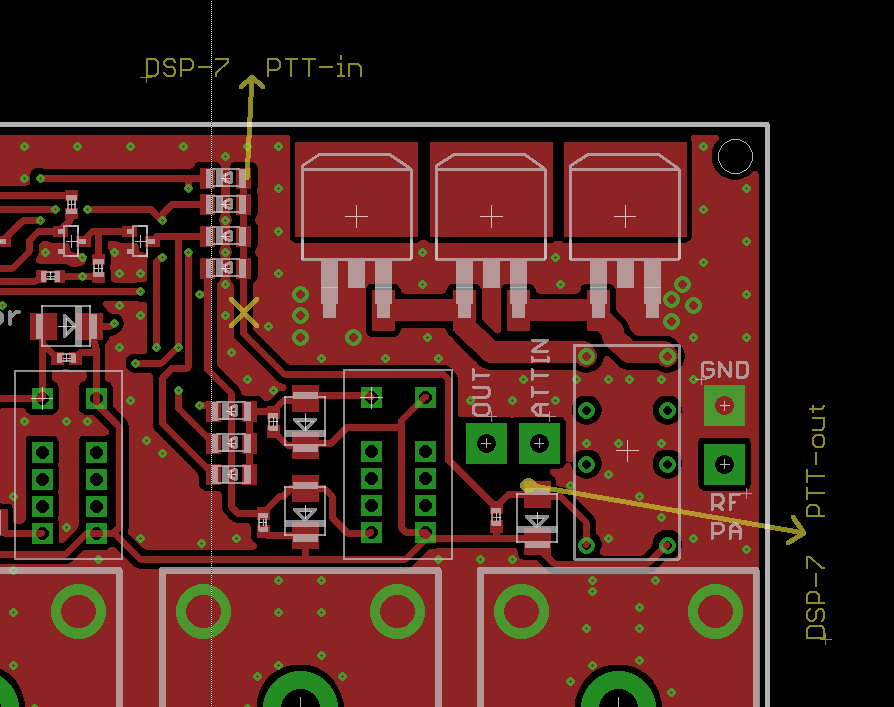
This modification enables another function: if the PA is automatically shut down due to some fault, the transceiver will be switched directly to the antenna (via the low-pass filter). So you can still complete your QSO (with less power).
Show selected TRX and use CAT with DSP-7:
With DSP-7 firmware 1.4 or higher you can show the actually selected transceiver on the screen. Additionally you can connect all your Icom transceivers to the CI-V interface of DSP-7 and DSP-7 will automatically read the frequency of the selected transceiver. To make that work you need four wires:
Connect one end of the wires to the PTT-1 (PTT-2, PTT-3 and PTT-4) line, in parallel to the four wires going to the transceiver selector board.
Connect the other end of the wires to DSP-7, see this picture:
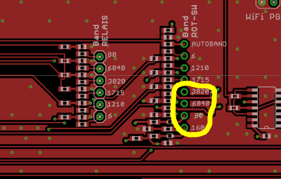
* Look for the connector "Band ROT-SW", the 8-pin header.
* connect PTT-1 to the pin "160"
* connect PTT-2 to the pin "80"
* connect PTT-3 to the pin "6040"
* connect PTT-4 to the pin "3020"
To activate this function go to DSP-7's menu SYSTEM-2 and set the AUX
input to "PTT 4x".
If you have Icom transceivers connected to the CI-V interface then enter the
CI-V addresses of these transceivers.
Design-Sample, stainless steel case built by DL1EV: