LDMOS power amplifier
Overcurrent Protection
Like
most of us,
I use one of these HP server power supplies, which can deliver 50 volts with 60
amps of power. The
50 volts are still low voltage, but the maximum current of 60A can have a heavy
impact. Just
imagine a broken cable, a broken-through transistor or similar. The
power supply mercilessly pushes this 60A into the load. Only
when a short circuit is detected the power supply switches
off. If
(!)
it is detected, because that works only with really low-impedance wiring and a
low-impedance error. Otherwise,
a continuous current of just under 60A flows and the power supply does not
switch off. The
consequences are easy to imagine. 60A is enough for welding, as it bangs in the Shack, but heavily.
In order to prevent such danger, there are essentially 2 solutions:
a)
The wiring must be made thick enough
that
a high short-circuit current can flow in the event of a fault. Only then the fuses in the power supply recognize the fault
and switches off.
b)
the maximum current should be limited by an additional hardware
to the really required level.
A readily built and tested board is
available at www.helitron.de/shop
Overcurrent
protection:
The overcurrent protection switch described here is looped into
the positive line between the power supply and the power amplifier. With
a resistor you can set the required maximum current. If
this current is exceeded (even for a short time) then the switch opens
permanently. You then have to turn off / on to reset the
circuit breaker.
the circuit is
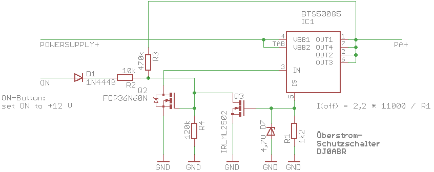
based on the high-side switch BTS50085. This type
withstands the required voltages and currents.
Function:
To switch on, put
the line ON on the usual + 12V. I have an "ON" button
on the front panel.
This will trip Q2 and pull Pin3 of the BTS50085 to ground. Now
the BTS switches on and the supply voltage reaches the PA. At the
same time a self-locking is made via R3, so that you can release the ON button
again, the BTS remains switched on.
At pin5 the resistor R1 is connected. The BTS50085
generates a current flow through R1, which is derived directly from the load
current. It is therefore possible to use the voltage drop across
R1 as an indicator of the load current. As soon as the
voltage at R1 reaches the threshold voltage of Q3 (about 2 to 2.5V), Q3
becomes conductive, as a result Q2 blocks, causing the BTS50085 to open and
the load current is interrupted.
If the power is interrupted, you have to press the ON button again
to turn it on. Of course you should first eliminate the
cause of the high current.
Adjustment:
The circuit
requires matching because both the threshold voltage of Q3 and the current
through R1 are subject to greater tolerances. The threshold
voltage can be found in the data sheet of the Mosfet used (transfer
characteristic).
The switch-off
current is calculated as follows:
I (off) = U (threshold) * 13000 / R1
where the factor 13000 can be in the range of 11000 to 15000 according
to the data sheet of the BTS50085. For my copy it
was 11000.
The best way is to
assemble a
2.2kOhm resistor first and check at which power it is
turned off. It will happen somewhere at 6A to maybe 10A. Now
you have a clue and can calculate what factor the BTS50085 actually has:
Factor = I (off) * R1 / U (threshold)
Now that you know the factor, you can easily calculate the required
resistance with the first formula.
I set the current limit to 30A and had to install a R1 of 820 ohms.