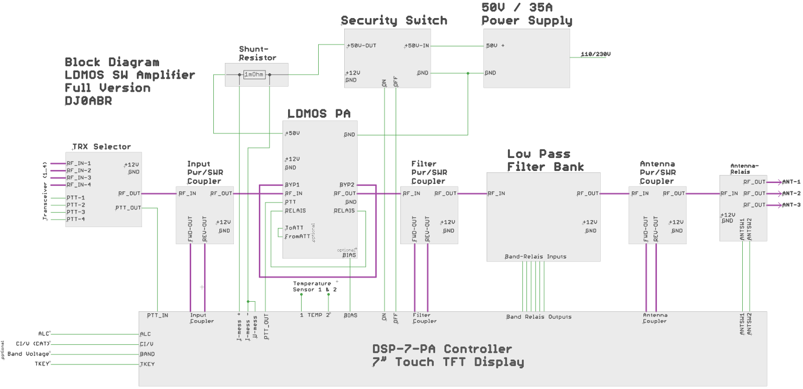
All modules described here are ready and available. To keep track, here is a block diagram and a description of the interconnection:
Resolution 1600 pixel: see HERE
HiRes picture: see HERE
violet
connections: coaxial
cable
green connections: normal wire
RF from Input to Output:
Up to 4 transceivers can be connected to the TRX selector module. Pressing the PTT switches the input to this transceiver. (The module is of course optional, you can also use a manual switch).
Next the RF goes to the Input-Pwr/SWR coupler. The purpose of this coupler is to monitor the input power. If you set your transceiver to 100W output and send into the amplifier there is a good chance to generate some smoke and burning components. Using this Input Pwr / SWR coupler the controller can turn off the PA in case of failure and connect the transceiver directly to the antenna.
From the coupler the RF goes directly into the PA.
Since the TX power of the trasceiver is practically always much too high, we need an input attenuator. There are two alternatives: The PA has the connectors FromATT and ToATT, where you can insert a 10dB attenuator made of standard 3W resistors. But if you use the TRX selector module, then this attenuator is already provided there. In that case you can connect FromATT and ToATT directly together.
The PA is followed by another coupler, the Filter-Pwr / SWR coupler. The purpose of this coupler is to detect a wrongly switched or defective filter. If possible you will have the filter switched automatically. Nevertheless, it eventually happens that you choose the wrong one, and then this coupler helps preventing damage, as the controller shuts down immediately.
From the Filter-Pwr/Swr it goes into the filter bank. There are 6 switching outputs available which are sufficient for switching 7 filters. The controller has different band combinations and therefore supports different filter configurations.
Next to the filter follows the third coupler, the Antenna Pwr / SWR coupler. Here, as usual, power and SWR are measured at the antenna output.
The last module is the antenna switch. If you have more than one antenna, the controller can automatically switch to the right antenna depending on the band.
Power Supply:
The output of the 50V power supply is connect to the safety switch. Apart from switching on / off the PA supply, this switch can interrupt the supply in a very short time when an adjustable load current is exceeded. This is important for safety and health. This security feature should always be used, also for protection of the expensive LDMOS transistors. The controller can switch ON the 50 V supply via the ON / OFF lines and switch it OFF immediately in case of failure (emergency stop mode).
A 1 milli ohms shunt resistor is inserted between the security switch and the amplifier. The current into the PA produces a voltage drop across the shunt which is measured by the controller. At the same time, the supply voltage is also measured via the connection U-mess.
Temperature Measurement:
two temperaturesensors (NTC type: B57703M103G) can be connected to the controller. One sensor is usually screwed onto the heat sink, the other as close as possible to the power transistors. At the first adjustable temperature level the fan or water pump is switched on. At another higher adjustable level the amplifier is switch off (Emergency off).
Antenna switch:
The controller DSP-7-PA allows the assignment of bands to antennas. The controller switches the antenna relays via the lines ANTSEL1 and 2.
other connections:
BIAS: the BIAS line is set to +12V a short time before the PTT line is activated. This volatge is used to generate the BIAS voltage for Mosfet transistors. In case of an emergency the controller switches OFF this BIAS voltage. (this connection is not used in my amplifier boards because the BIAS logic is already included in the PA board).
ALC: outputs a negative voltage to limit the power of the transceiver. Connect it to the ALC input of the transceiver. The level can be set with a potentiometer on the controller board.
CI / V: Icom CAT Interface. If this line is connected to an CI / V of an Icom transceiver, the band and antenna switching works fully automatic.
BAND voltage: If the CI / V interface of the transceiver is already in use, the automatic band switching can also be done via the BAND line which is connected to the DATA socket on Icom transceivers.
TKEY: the TKEY line is used by remote controlled tuners to indicate the tuning process. If this line is connected to the controller, then the power amplifier is automatically switched off during a tuning process and the transceiver is connected directly to the antenna..
other wires on the amplifier board:
RELAIS: These two connections are connected by a simple wire. It is the control line for the output relay to activate it during transmission.
BYP-1 und BYP-2: These two connections are connected with a piece of thin coaxial cable. The antenna signal goes in RX mode via this line.