When the controller is switched ON, it starts with a welcome-screen and all functions are switched off and disabled (with the exception of the fan control if the cooler is already hot).
If a power relais is used the supply voltage of the power amplifier is also switched off.
The only available control is the ON button. Touching the ON button will switch ON the amplifier supply and the controller is in standby mode.
Operating modes:
Standby: the power is switched ON. The transceiver is directly connected to the antenna, the amplifier is inactive and pressing the PTT has no effect.
Active: the system is waiting for the PTT. When the PTT is pressed the RX/TX relais will switch to TX and the amplifier is fully working.
Emergency-OFF: when the OFF button is pressed or if an emergency situation occures the controller goes into emergency off mode, everything will be switched off. Correct the error situation and press ON to reactivate the system.
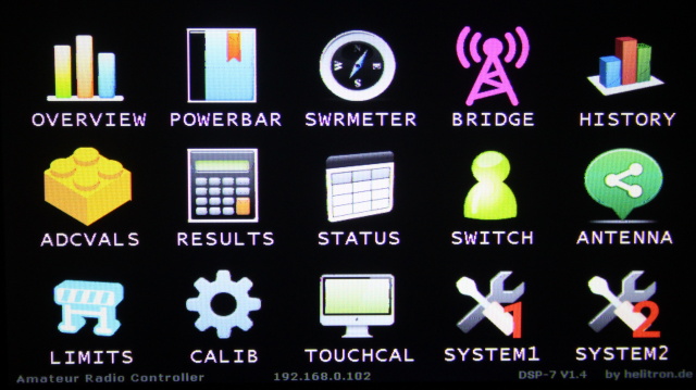
If the ON button is pressed after power-on, the controller shows the power-bars screen. Now touch the "MENU" button to enter the selection menu:
here you can navigate to all functions and screens of the DSP-7 controller.
Buttons at the bottom:
Emergency OFF: switch everything OFF.
ACTIVE: switches to active mode, the amplifier can be used
STANDBY: switches to standby mode, the amp is standby but cannot be keyed by the PTT. The transmitter is connected directly to the antenna.
MENU: shows the main selection screen
Buttons at the right:
The Band Selection buttons are used to switch to a band. This automatically select the lowpass filter band and the antenna (if configured). The AUTO button can be used if an ICOM transceiver is connected via CI/V interface or via the BAND output line.
The assignment of antennas to bands is done in the antenna-screen, as described below.
The assignment of lowpass-filter-banks to bands is done in the SYSTEM menu and is described there.
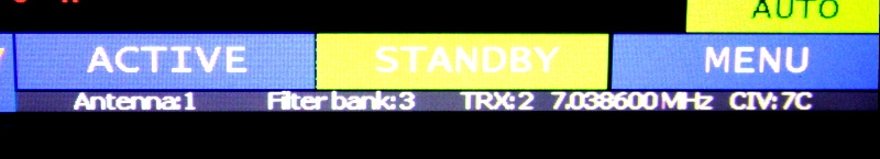
Status line at the bottom:
it shows to active antenna if you use an antenna relais board and if you have setup the antenna menu.
Then it shows the active low pass filter bank. DSP-7 supports 7 filter banks which can be used by multiple bands.
If you have connected an Icom transceiver to the CI-V interface then the frequency and the CIV-address are displayed. If the transceiver selector board is used, it shows which of the (up to) 4 transceivers is in use.
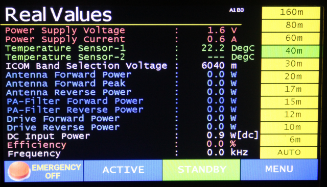
OVERVIEW:
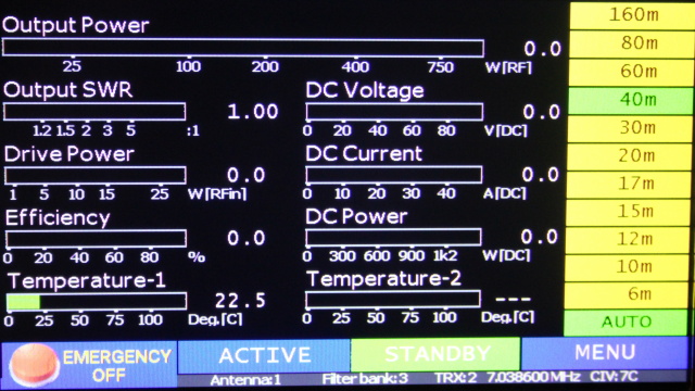
this screen shows the most important values for the operation of the amplifier.
Like in all other screen the bargraph shows the mean power value and the number shows the maximum value.
POWER BAR:
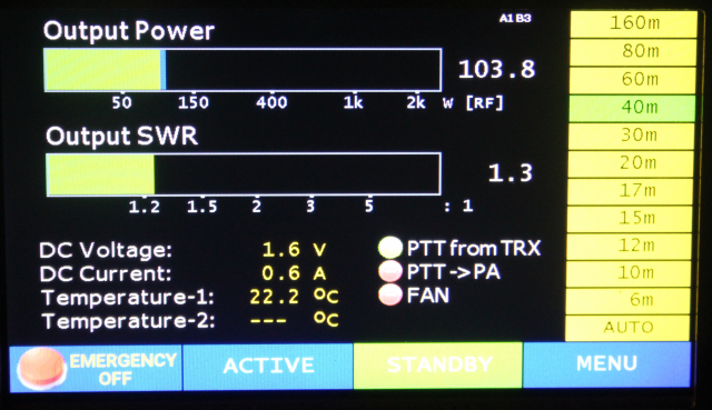
shows power and SWR using large and easy to read bars.
SWRMETER:
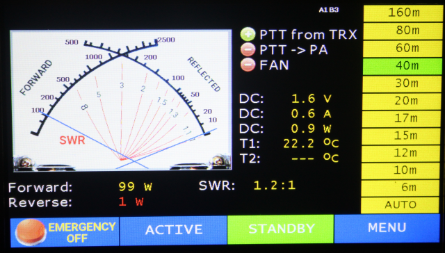
shows power and SWR in a photorealistic simulation of an analog cross-needle instrument as well as some other measurement values.
BRIDGE:
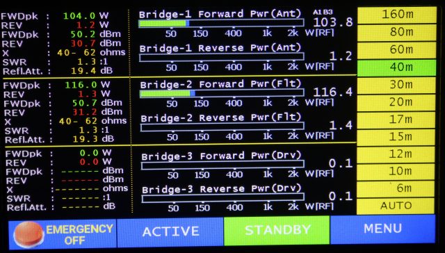
give a complete overview about all three power/SWR couplers as well as some calculated values like reflexion attenuation and others.
HISTORY:
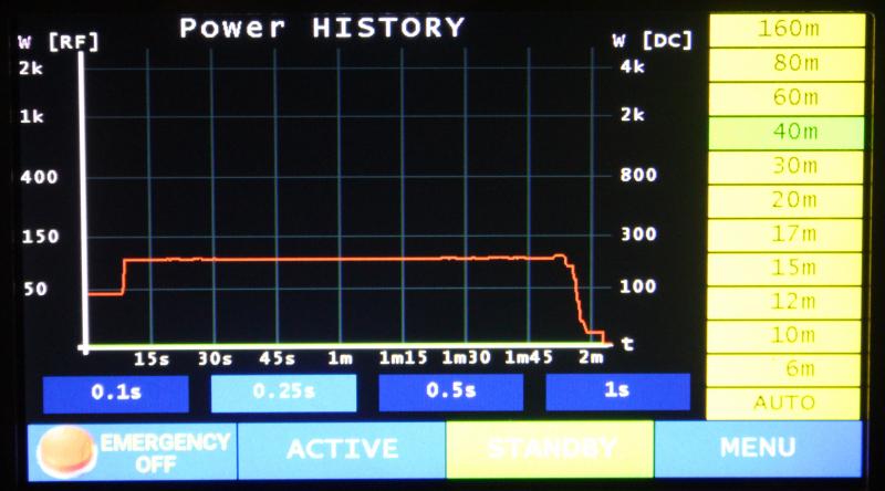
shows an history of the output power (red) and the DC input power (green).
ADCVALS:
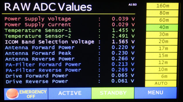
this screen shows the raw values measured by the on-board AD-Converter. It can be used for installation and debugging purposes.
RESULTS:
this screen shows the values of the AD-Converters, but (in difference to the previos screen) the real values are calculated from the raw values.
STATUS:

this screen shows the state of the various digital inputs and outputs. It is very useful when building the amplifier. You can see if relais should be activated or not, a very important screen.
SWITCH:
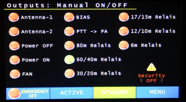
this screen lets you switch the outputs manually. Attention: when this screen is open the automatic security functions are deactivated. Use it only for testing purposes during building and debugging your amplifier.
ANTENNA:
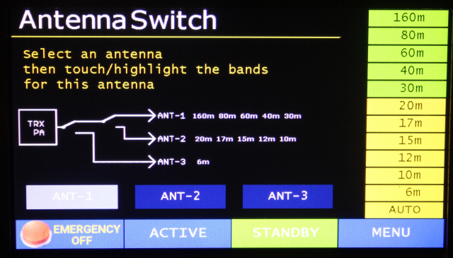
using this screen you can assign bands to antennas. The controller has two antenna output ports for two relais. Using these two relais we can connect up to three antennas to the amplifier. The schematics on the screen shows the state of these relais. Select an antenna ANT-1 to 3 and then activate or deactivate to bands for this antenna.
LIMITS:
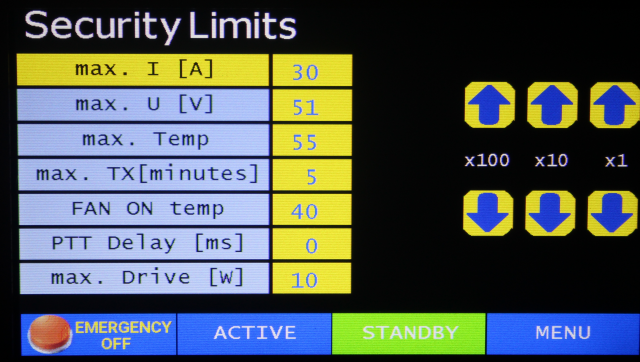
these are the limits for the security features:
max. I [A] ... the controller will enter emergency-OFF when this
current is exceeded. Additinally I recommend using the security
switch.
max. U [V] ... the controller will enter emergency-OFF when this current
is exceeded
max. Temp ... the controller will enter emergency-OFF when this
temperature is exceeded by one of the two temperature sensors
max. TX [min] ... the controller will enter emergency-OFF when it is
keyed and transmitting longer then this time
FAN ON temp ... if one of the temperature sensors exceeds
this temperature the FAN output will be switched on. It will be switched off if
the temperature is 4 deg lower then this value.
PTT Delay [ms] ... keying the amplifier is delayed by this time in
milliseconds. This delay can be used to first switch on the Mosfet's bias
voltage and then activate the PTT.
max. drive [W] ... the controller will enter emergency-OFF when
this drive power is exceeded (an input power/swr bridge must be installed for
this feature).
CALIBRATION:
the calibration process for power/SWR couplers is described on THIS page.
TOUCHCAL:
this screen is used to calibrate the touch sensor of the 7" display. Use a ballpoint pen with retracted mine to touch the screen during calibration. This give much better results then doing it with a finger.
ATTENTION: with Firmware Version 20.12.2017: before calibrating the display go into the SYSTEM menu and set "Display Reverse" to "REVERSE. Then calibrate the display. And finally restore the Display Reverse setting to normal.
SYSTEM MENU 1:
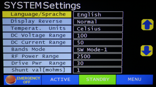
this screen has various system settings:
Language ... the DSP-7 has English and German language included.
Please contact me If you need another language, the firmware is able to handle
any latin language if someone helps with translation.
Display Reverse ... turns the display (and touch) 180 degrees. The
contrast and readability of the 7" display is different from top or bottom.
It is possible to mount the DSP-7 upside down and then mirror the display using
this setting.
Temperat. Units ... select Celsius or Fahrenheit. The temperature
settings in the LIMITS screenalso uses this unit.
DC Voltage Range ... this controller handles a huge voltage range. In
addition to this setting a voltage devider must be connected to the Um input.
See the connections-manual for details.
DC Current Range ... this controller handles a huge current range. In
addition to this setting the shunt resistor can be modified. See the connections-manual
for details and the Shunt setting below.
Bands Mode ... offers various band <-> filterbank combinations as
described below
RF Power Range ... this controller handles a huge RF power range. Your
Power/SWR coupler must be usable for the required power, of course.The only
requirement is that your coupler generates a forward/reverse voltage between 0
and 2.4 volts over the full range.
Drive Pwr Range ... same as above, but this is a separate setting since
the drive power is usually much lower than the output power.
Shunt val[mohms] ... value of the shunt resistor used for current
measurement.
Assignment of Bands to filter banks:
this controller has 6 outputs to switch up to 7 filter banks (Bank-1 is selected if no relay is energized)
For short wave amplifiers there are four different Band -> Filterbank types available. Choose the Band Mode selection as follows:
| Filterbank Relais | SW Mode-1 | SW Mode-2 | SW Mode-3 | SW Mode-4 |
| no | 160m | 160m | 160m | 160m |
| 1 | 80m | 80+60m | 80m | 80+60+40m |
| 2 | 60+40m | 40+30m | 60+40m | 30m |
| 3 | 30+20m | 20+17m | 30m | 20m |
| 4 | 17+15m | 15m | 20+17+15m | 17+15m |
| 5 | 12+10m | 12+10m | 12+10m | 12+10m |
| 6 | 6m | 6m | 6m | 6m |
Example: if SW Mode-1 is selected and you switch to the 30m band then the relais output 3 will be activated.
Contact me if your filter bank requires another configuration.
SYSTEM MENU 2:
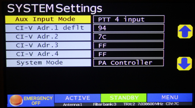
this screen has additional system settings:
Aux Input Mode: There are four input connections which have alternate functions. Refer to the Connector-Manual and look for "BAND ROT SWITCH, Alternate Functions". These connectors may be used as an input for a rotary switch to select the filter bank. Or alternatively it can be used as additional 4 PTT inputs (mandatory if you use the automatic transceiver selector board).
CI-V Adr.1 deflt: This is the default CIV-address if you connect one single Icom transceiver. Set this value to the CI-V adress of your transceiver. The baud rate is 4800 Bd.
CI-V Adr.2 ... 4: these additional CI-V adresses are used if the Aux Input Mode is set to "PTT 4 input". By connecting the alternate inputs to the PTTs of up to 4 Icom transceivers DSP-7 automatically uses the CI-V address of the currently active transceiver (mandatory if you use the automatic transceiver selector board).
System Mode: DSP-7 can be used for two different applications. 1) as a Power Amplifier Controller or 2) as a display for a triple Power/SWR meter. While the basic functions of DSP-7 are the same in both modes, the display shows different controls optimisedfor these modes..